Laser Cutter Build Night: Almost Complete!

Tonight was an extremely productive and satisfying build night.  After the success of last night, I absolutely had to see this project through.  I did quite a few things:

First, I fixed the sticking problem, hopefully once and for all.  I took apart the entire XY table sled assemble and cleaned everything with rags, water, and a toothbrush.  Then, I generously slathered everything in mineral oil.  Quite generously, actually.  The parts were so slippery they nearly jumped out of my hand.  After putting everything back together, the problems dissolved and haven't reared their ugly heads since.  I am quite happy about this, since the X axis had become unusable due to its sticking problem.

I also added anti-backlash code.  To do this, I set a variable to keep track of the direction the motor moved last.  If the new direction for the motor to move is opposite its last direction, the motor moves a few hundred extra microsteps in the new direction to counteract the backlash.  It does not update its position variable, because the actual axis has not moved relative the the laser beam.  I was able to use this new functionality quite effectively to eradicate all backlash on my X and Y axes.

Finally, I did some test code.  The axes never stuck and my circles came out perfectly circular.  I also figured out how to do complicated drawings using Inkscape and the laser cutter extension, so I had my machine do an amazing job of drawing its name (click the picture for a bigger view):


That engraving of the name "PiKnife" represents so much - the culmination of hours and hours of work.  It means so a lot to me to finally have a beautiful piece of proof that this actually does stuff.  I was truly amazed when I saw such fine, curving lines meeting up perfectly.  I look forward to a lot of future use of this machine.

My next goals will be to add in the limit switches and look into the timing issues.  However, neither of these affected the engraving above, so I am currently a very happy engineer.

Experiment 29: Lost Foam Casting a Slingshot

After seeing some cool videos on lost foam casting and also becoming addicted to Joerg Sprave's videos on YouTube, I decided that I had to try this method of metal casting.  I used some StyroFoam as my foam material to carve into a slingshot and then put it in sand for casting.  After pouring, it turned out quite well!  It has a few pits and imperfections, but it looks pretty awesome otherwise.  Although its rubber doesn't perform very well in the wintry cold, it should be powerful enough for squirrel hunting in the spring and summer.  I look forward to blasting some stuff to tiny bits as soon as it warms up!

Also, check out its Instructable for more detailed information!  If you want to watch the pour, check out this video and this ingot casting video on my YouTube channel.  I have included a few pictures of the casting session (I also cast a few nice-looking ingots in the same session):


Laser Cutter Build Night: It Works!!!!

After many unproductive and dissatisfying hours of trying to modify the code I downloaded off of here, I finally gave up, realized that the code was never going to work with my setup, and began to completely rewrite two of the files I downloaded.  If you look at the code, you will see that there are three files: Bipolar_Stepper_Motor_Class, Motor_control, and Gcode_executer.  I totally rewrote the first two.  Bascially, my code uses threaded programming in Python to make both axes move at the same time.  This is what makes diagonal lines instead of just a bunch of "staircase" lines imitating a diagonal line (these happen if you only drive one motor at once).  I will be posting my code very shortly; however, it isn't done yet, so I will wait on that.

Rewriting the code and testing it to debug it wasn't as hard as I thought.  I found that typing up a document in a text editor outlining what my code would do helped a lot.  It kept me on track and gave me some room to think about what the code actually had to do before jumping in.  I only had a few bugs to fix - division by zero (added an if statement to catch that case) and syntax errors.

When I tried the code, I was amazed to see that it actually worked!  It successfully drew the circle I told it to draw using G-code and even cut it at a reasonable pace instead of super-slowly!  Elated by my long-awaited success, I drew a sort of ninja star in a box using Inkscape and then converted it to G-code using the instructions provided here.  Amazingly, it worked!  Mostly, that is.  For some odd reason, the center circle of the ninja star and one of its arms were about an inch away from the real center of the ninja star.  I theorize that this could have been because of one axis getting stuck, because when the program went to the home position, it actually stopped about an inch away from the limit switches (still have to code those in).  What this means is that the code thought that the stepper was moving when in reality it wasn't; thus, when it told the motor to move x steps to go home, it didn't reach home because it the motor was farther from home than the software thought it was.

There are a few minor bugs to work out (besides fixing the sticking problem, or whatever else caused the ninja star misplacement).  I noticed that my circles I cut had flattish parts on them along one axis of movement.  I think that this is caused by the minor backlash issue I have - when one axis has reached the "vertex" of the circle along its axis of movement, it should turn around and start moving the other way.  Backlash causes it to go straight for a few hundred steps as the motor is rotating in its backlash.  Adding some simple code to detect change in direction should fix this.

Timing is another issue.  It was probably the biggest issue with the ready-made code, and it is possibly still a minor issue with mine.  Sometimes one axis will finish its movement to a point before the other finishes its movement to a point.  Additionally, when doing very small, detailed movements, the laser seems to move more slowly than when it is doing a "line drive" by moving a large distance in one move command.  I believe that this these issues are caused by minor mishaps in timing and tiny bits of lost time here and there in the thousands of start and stop movements required for fine detail.  I'll have to see if I can alleviate this issue; it may not be entirely correctable.

Experiment 28: DIY scientific ampoules!

In the near future, I plan to make elemental iodine for my element collection.  To effectively store iodine long-term, a hermetic (airtight, perfect) seal is recommended.  Scientific glass ampoules then, are perfect for storing iodine for years and years, like in a periodic table display.

In this experiment I made two glass ampoules myself from miniature test tubes.  I held the test tube by its bottom end with gloves and then torched the tube about 1cm from its mouth.  A propane blowtorch works well for this purpose.  I rotated the tube a few times to evenly distribute the heat in a band around the tube and in about 30 seconds, the tube softened.  I then used pliers to pull the mouth of the tube away from the rest of the tube by a few centimeters.  Then, I slowly removed the test tube from the flame, letting it gradually get cooler.  The end result was absolutely spectacular given the easiness of the experiment:


When the tubes are filled with crystal iodine (I will pour it down the thin neck of the ampoule), I will hit the narrow neck of the ampoule with the hottest part of the torch flame to rapidly melt it without heating up the iodine.  Then, I will use pliers to pull the neck of the ampoule completely off, thus sealing the iodine inside.  I am quite pleased to have such an easy way of making ampoules for chemistry stuff!

Experiment 27: Key Duplicating by Casting

I have always wanted to give key copying a go like the secret agents do in spy movies, so I tried it using my house key.  Before you freak out and say that key copying is illegal, note that I used my house key, which I own.  Do not copy other people's keys.  That is probably illegal and could be a felony.
Anyhow, I used some creative methods to quickly copy the key and cast it in zinc.  After a bit of touching up, the casting actually worked!  Check out the Instructable for pictures and more information!  Also, if you don't believe me, watch this video of the test in my door:

Update to YouTube Account Suspension

Bleh.  YouTube has not contacted me once about why my account was suspended, nor have they given the ScienceWithScreens channel back.  I am thouroughly disappointed with how they have handled this issue.  It should have been corrected months ago, since I never did anything wrong.

What I find strange is that using my normal email address (which I used for the ScienceWithScreens channel) I am still able to get into YouTube, just not into my old channel.  Odd.  Apparently, YouTube doesn't hate me enough to completely ban me. :)

This means that I will be uploading more science videos to the new channel YouTube gave me under the same email, located at this address:

I am super happy, and I hope you are, too!  Look forward to some really cool projects I have up my sleeve.  I will also fix all those "broken" videos that now exist on my blog.

Laser Cutter Build Night: It's a Fixer-Upper...

So my grand plans of spending this coming Saturday laser cutting amazingly complex and smooth curves, swirls, text, and other shapes isn't exactly going to work out.  The code I modified works, but it is a real fixer-upper.  At first, after a few edits of syntax errors, it did technically move the stepper motors... I would have been dead and gone by the time it actually finished.  I had to place a finger on the motor rotor to feel if it was spinning or not.  It was simply too slow to even notice with the human eye.

After a bit more modification, I "successfully" cut some ovals into some paper using Inkscape and a laser engraving extension to generate gcode.  The Python I modified did make ovals, they just didn't close off and looked more or less scribbled by a toddler.  In addition, the extremes I had to go to to make it work made the movement extremely jittery, although not by the stepper's fault.  I would have taken pictures but it is 11:14 PM and I'd better be off to bed sometime soon.

I will be working to try to salvage this code and if it doesn't work I suppose I will have to think something up.  This is going to get interesting...

Laser Cutter Build Night: Code (Hopefully) Completed!

Tonight I looked over the code and in basically one sitting modified it to a point where I think it should work.  The task was really quite easy, actually!  The man who wrote it was nice enough to leave extensive comments that were helpful in elucidating the meaning of the complex variable names and mathematical equations.  I still don't understand the stuff for drawing circles, but I don't need to modify that code, so who cares?  All I really had to do was change the bipolar stepper motor class to use pulses and direction high/low logic rather than using four inputs to manually step through the motor sequence.  I also deleted the unhold() function that released the holding power on the motors because I didn't have a way to port that to my EasyDriver setup easily and didn't see it as necessary.

A word of warning - I haven't actually tested this code yet!  It is late at night and I have other business to attend to.  Hopefully, I can get the code tested soon.  I noticed that it doesn't use limit switches at all, so I might be able to improve by adding support for those and potentially also for PWM laser modulation to set the intensity of the laser rather than just going faster/slower to engrave/cut.  I didn't bother to post my modded code because it is untested.  However, once I test it, I will post some download links.

Lastly, I sacrificed a black foam food container to the hungry red beam of my laser cutter.  I made five of drawMrSmiley() cut all the way through the foam.  They were pretty sweet looking, but I gave them away to inquisitive people before I photographed them.  This foam cut like butter - even more quickly than the craft foam - I almost couldn't go fast enough to prevent a full cut.  PWM should help!

Laser Cutter Build Night: Hardware Finished!

Tonight I completed all the hardware for the laser cutter and confirmed that everything is working!  I fixed the little issue with the X axis by cutting off the offending portion of the platform support and then retaping the entire platform back on to the moving sled.  Also, just for fun, I engraved drawMrSmiley() on the bottom of one of the MDF supports.  It engraved quite nicely.

I also made some workpiece holders out of small neodymium magnets and hardware nuts.  I saw this idea somewhere online - it wasn't my invention.  These will hold nicely on to the sheet metal platform and hold down the workpiece so it doesn't squirm under the intense heat of the laser. :)


As you can see, the magnets work quite well.  On the right are the seven drawMrSmiley() pieces of cardboard I engraved as a sort of stress test.  They all came out quite well and none of the electronics got too hot.  I ended up giving them to friends.  With the cardboard engraving, I noticed that if I set the speed to be too fast, the laser would sort of "skip" parts of lines because it didn't have enough time to fully burn the path.

I also made a really awesome looking bookmark by cutting (rather than engraving) blue craft paper.  I used some "for" loops to iterate through the area of the bookmark.  The laser cutter ended up making 900 holes.  Heh heh heh.  I like this machine.  :)
I am sure glad I didn't cut those by hand!  Even so, it took a few hours to complete.  However, I like that my laser cutter can cut all the way through the paper.  I'd like to point out that I programmed the code to cut squares, but it ended up making rectangles.  This was because of the slight backlash issue.  Basically, the backlash caused on side of the square to be cut shorter than the other, which affected another side, causing the square to squish just a bit.  Not a big issue, though.  Software to the rescue!

So, all the laser cutter hardware is complete.  I am extremely happy with how it turned out!  I also am looking forward to further enjoying its surprising cutting capabilities.  The tiny laser packs a punch!  Looking into the future, I will be starting to modify the downloaded code that reads gcode and moves the motors.  It shouldn't be a very hard task.

Laser Cutter Build Night: Electronics Attached, Hardware Ready to Go

Tonight was a very productive night!  After the encouraging cutting results of last night, I attached the Raspberry Pi, EasyDriver, and laser driver boards to the laser cutter plywood base.  I used screws and nylon tubing standoffs for the Raspberry Pi and hot glue for the laser driver.  However, since I blindly followed this guide for assembling the EasyDriver pin headers, I had pin headers on the top and bottom of these boards.  This made attachment complicated, because I had wires below the circuit board.  To get around this problem, I raised the EasyDrivers off of the base by sliding their mounting holes over sharpened chopsticks and securing them with hot glue.  I did the same thing for the computer fan that cools these electronics.  I decided not to use an enclosure because of the hassle of managing all the wires inside such a small space and also because of the difficulty of preventing large stresses on the connections.


Looks pretty sweet!  I like how the fan is aligned diagonally to the other boards.  Additionally, I noticed that the LM317 on the laser driver was painfully hot during its tests with the dummy load (this simulates the laser; read the previous post for details), so I used the failed laser diode heatsink to cool it.  I also used a bit of zinc oxide baby cream to stand in for thermal compound.  I believe I read somewhere that this is a good substitute because zinc oxide is the main ingredient in commercial thermal pastes.

As you can see in the pictures, I am using a ribbon cable to attach the control system electronics to the Raspberry Pi.  This will enable me to semi-easily remove and replace the Raspberry Pi if I need it for other projects.  A cheaper controller would have been nicer because then I could just leave it on the laser cutter forever.  However, since I spent upwards of $50 on the Pi and all its extra peripherals and power accessories (and since I only have one), I don't really want to leave it there forever.

I also epoxied the power switch to the edge of the base so it is nicely accessible and stable.

After I completed all these tasks, I looked into the X axis stalling issue.  After a cursory debugging run-through, I found the problem.  The base of the moving platform was running into the Y axix stepper motor when the X axis got to a certain position.  Stupid me.  *Sigh*

Finally, I coded a test function to ascertain the engraving/cutting capabilities of my laser cutter on different materials.  I called it "drawMrSmiley()".  Using this, I can set a cutting speed and an engraving speed and see if it works on different materials and colors of materials.  The square is cut and the face is engraved.  The laser also engraves wood!  I am quite exuberant at these impressive results!


From top to bottom left to right are offwhite paper (engraving speed was too fast), green fabric, green craft foam, and black craft foam.  I also did a cool zipper/zigzag design on wood.  I love this laser cutter!

Laser Cutter Build Night: Permanent Laser Driver Circuit

So, as it turns out, the previous laser diode was totally dead.  That is to say, I really messed up on its soldering, the wires came off, and the stored charge in the capacitor blew it.  However, in a record display of resilience, I removed my 3rd diode from its DVD sled and put it in the Aixiz module after removing the dead one.  Then, I soldered and tested it and it worked!  It can burn!  Bwa ha ha ha ha!

Next, I set about figuring out what current I wanted to run the diode at in the long term.  I had been using 3.3 ohms of resistance for a set current of 375ma, but I read differing views on whether this was too high for a DVD burner diode.  As such, I decided to just try 5 ohms of resistance for a current of 250ma (watch this video for why the current changed with the resistance) and then see if the burning power was significantly decreased.  Using less current, I observed about the same burning power, so I decided to play it safe and go with less current in the long run.  If you have seen other LM317 driver circuits, you know that they use a potentiometer to further control the current.  I am omitting this, because I really don't see why I would adjust the laser power when it is cutting.  Thus, I have set it permanently to be at a good power level.

After that, I planned out how my laser driver circuit would look taken off the breadboard and put on some protoboard stuff I had lying around.  I used graph paper for this.  I wanted to make it as small as possible in order to conserve protoboard for other projects/lasers and also just because I could.  I used this schematic (omitting the reverse voltage diode and potentiometer).  As explained in this post, I also added a transistor to turn the laser on/off.  Eventually, I ended up with this tiny circuit:


It is very small!  However, I would like to point out that small is not necessarily the way to go, nor is soldering at 7 in the morning.  It was somewhat difficult doing the delicate soldering needed to maintain a solder bridge-free circuit.  Additionally, since I soldered at 7 in the morning, I neglected to actually solder the positive of the laser output to the rest of the circuit.  That is only slightly a big deal. :)  I spent a few days saying "Woe is me" etcetera because I couldn't get it to work, no matter what.  Thankfully, I was using a test load to test the driver, instead of the real laser diode.   This is described here.

Anyhow, I eventually got the driver to work, and it works beautifully!  I never knew my laser had so much power!  Maybe the 3.3 ohms of resistance was 
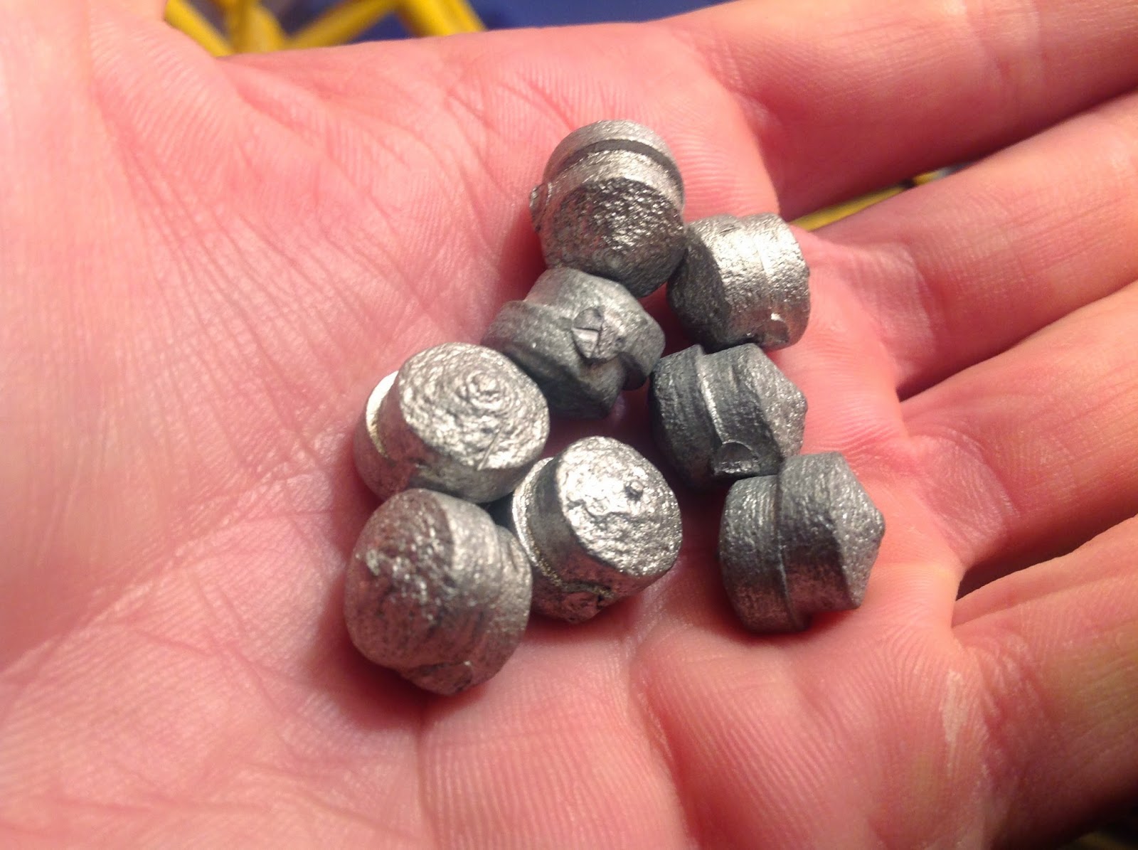
worse than the present 5 ohms?  Now my laser can easily cut all the way through black craft foam with ease, in one pass.  Clean cut, all the way through!  Slices like butter.  Below is a picture of the foam mincemeat I made while playing with my laser.


As you can see, I thought that the laser deserved a sticker (I got it from HighTechDealz.com free with my order).  I am very happy with its destructive power now! :)  Also, I actually laser cut the right side off of the sticker, because the sticker content was way off center.  Now, my laser cutter has done something useful and shown that it can even cut white paper!  Not plain white paper, though - I tried regular printing paper, but it didn't cut it like it did with the sticker.

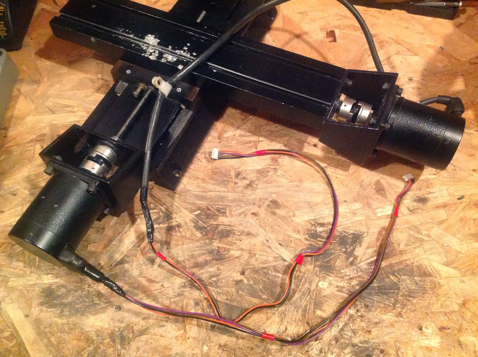
Next, I will be securing the electronics of this project onto the plywood base and enclosing them in a box with the computer fan on top for cooling.  I will also be fixing an annoying issue that sprung up (there always has to be some problem, doesn't there?) with the X axis where the motor gets to a certain point and then jitters/stalls.  I am crossing my fingers for WD40 to do its magic.

Finally, for your viewing pleasure, I have included an iPad video taken of the laser cutter decimating a string of bits of craft foam.  Enjoy!

Laser Cutter Build Night: Two Steps Forward and...

So tonight was really an example of the two steps forward and one step back rule, except that I am almost certain I went at least two steps back.  In regard to my two steps forward, I cut the final base for my laser cutter, so now have something permanent to attach things to.  I also attached the XY table and the laser stand.  This laser cutter (rather than one that moves the laser beam itself) is very interesting, as the laser is stationary and the material to be cut moves.  Thus, the laser diode has to be off-center relative to the XY table in order to cut the maximum area of space.
 Also, I made my first successful engraving!  I hard-coded a smiley face into my stepper, laser, & limit swtich test program using basic move X and move Y commands.  I am quite pleased with the results!  The only problem I noticed was a tiny bit of backlash in one cut (click on the image to enlarge and see the backlash on the right eye), but that isn't a big issue right now, as I have far larger problems...
Those are my two steps forward.  Attaching stuff and engraving.  Then, everything went really steeply downhill!  First, I noticed that my cutting area is not one normal sheet of paper, as I had previously predicted.  This laser cutter will actually be able to engrave/cut an area between 1/2 and 1/4 of the size of an 8-1/2"x11" sheet.  The reason is this: even if I have a lead screw for moving the axes that is as long or as wide as the paper, if the sled that moves along the screw and carries the paper is wider than a geometric point (i.e. no width), it will not be able to traverse the whole paper's length without coming off the screw.

To make this clearer, let's say I have a screw 11" long and the sled that moves the cutting table is 5" wide.  The paper's edge is placed at the beginning of the 11" and the 5" sled is at the home position- the paper's edge, the start of the screw, and the beginning of the sled are all in the same position right now.  Then, the sled moves as far as it can, also moving the paper.  It cannot actually move so that the edge of the paper is 11" from its starting position - that would require that the beginning of the sled be at the tip of the lead screw - in other words, disconnected.  So, in reality, the paper can only be cut for 6".  That is basically what happened with my laser cutter.  One step back.

Additionally (this is more of a problem), my laser broke!  I turned it on and it was very dim and intermittenly shone.  Ahhh!  After walking away to "cool down" for a bit, I took off the Aixiz housing.  The laser power wires came off as well.  It seems that whatever problem I had was caused by a soldering defect (me).  Tsk tsk.  One demerit.  Tomorrow I will reattach the wires to the laser leads and try it out again.  The laser may be unharmed, but it is most likely damaged.  I read somewhere that disconnecting the laser diode (or letting its power wires come off) from an energized driver circuit can fry the diode because of the electricity built up in the capacitor.  At least another step back.  :(

"Sometimes, life smiles at you and says, 'I like you.'  Other times, it give you a sneer and says, 'I hate yo' guts, boy!'" -me

Laser Cutter Build Night: Laser Heatsink & Stand

Tonight I machined a nice little heatsink to replace the one that I drilled out too large.  This one is a solid block of aluminum that I salvaged from some machine that was being junked.  It should work well enough without fins, for my purposes at least.  I also made a hole for a setscrew and tapped it.  The whole thing turned out nicely and I like how it looks - clean and professional.  The Aixiz housing goes in the hole and is held in place by the setscrew.
 I also manufactured a stand for the laser.  You say, "A stand?"  Yes, a stand.  When I was building this, I realized that this must be the most unconventional way of building a laser cutter.  In nearly every other machine, the laser (or rather its beam, reflected by mirrors) moves.  My machine, due to its genesis as a CNC machine, moves the platform, not the laser.  This is somewhat annoying for multiple reasons.  One of these is that I may have to further modify the code I am porting to make it work with my unusual setup.  But, I am sure I will make it work!
I may eventually paint this to make it look nicer.  Additionally, I discovered that my laser can cut into black craft foam, slice a green ribbon in two, and etch black CD cases.  Maybe it isn't so underpowered after all!

Lastly, I began to look at the code I will be modifying.  I am using Python code from here.  I need to change the code from controlling bare H-bridges (which take four inputs) to controlling the EasyDriver stepper boards (which take one step input and one direction input).  It may be a challenge, but with the prize of a laser cutter at stake, I am sure I can do it!

Laser Cutter Build Night: Burnage!

It burns!  I finally received my Aixiz housing in the mail and assembled it.  I got mine from hightechdealz.com.  I had also ordered some of their free 650nm (red light) laser safety stickers, but honestly, they were very low quality.  They appeared to have been made on a home laser printer running very low on toner and then cut out by an unskilled toddler.  Hey, I guess they were free.  I would have been severely disappointed if I had paid for them.

Anyhow, the laser stickers are a tangent.  Once I had opened the package, I placed (set; not pressed) the diode into the housing to dissapate heat and desoldered the ribbon cable from the leads.  Then, I pressfit the diode into the housing and soldered on some long power wires.  After that, I assembled the laser housing, double-checked everything, and turned the laser on!

Thankfully, the lens I got focuses the laser instead of collimating its beam.  That way, I can get a very fine point for blasting away at the materials I will be cutting/engraving!  I was able to change where the focal point of the laser was by twisting the lens.

In operation, the laser housing becomes only mildly warm.  This is good, because the hole I made in my heatsink is too spacious.  I do not know if I will be using an external heatsink in the long run.

I tried cutting some electrical tape with the laser, and it smoked, but was nowhere near what I expected its power to be.  Eventually, I was able to cut some tape that was under stress (very slowly).   I also tried lighting a match colored black, and the match smoked, but didn't light.  Very disappointing.  However, with the adjustable focus, I can make black plastic smoke at a fair range.  Fun, but I need a lot more power.  The laser barely scratched some black business card material.

In looking into the problem, I will be evaluating increased current, shortened power wires, and, as a last resort, a $10 glass lens (mine is acrylic) from hightechdealz.com.

Laser Cutter Build Night: Moving Platform and Laser Preparations

Tonight was a bittersweet night.  I had previously attached my really nice build table with double-sided tape and it stayed on really nicely.  However, I failed to plan for the underside supports running into the stepper motor bracket.  To fix the problem, I removed the moving platform (it stuck really well!) and then cut off the offending section of support using a Dremel tool and cutting wheel.  I had heard that MDF dust was bad for one's lungs, so I held my breath for most of the cutting process.  That made it interesting.  After I cut through the board, I chiseled it off.  My perfect purple platform got scraped a bit, but it will still curtail laser reflections.  Pictured is the modified platform.


Additionally, I ordered my Aixiz laser module for heatsinking and protecting my red DVD burner diode.  I will hopefully be receiving this.  However, I haven't gotten it yet, so that sort of tables work on the laser cutter until the package arrives.  :(

As a tiny last bit of work to do, I drilled out an old transistor heatsink to put the Aixiz laser module in for additional cooling.  I used a 31/64 bit, which is the closest I could find to the 12mm module diameter.  I may add heatsink compound to the module before I slide it in, or I may just use a setscrew to hold it in place.
Sadly, that is about all I can do until my Aixiz module arrives.  *Pout face*

Laser Cutter Build Night: Functional Limit Switches

It's pretty late, so this post will be short.  However, I have successfully wired up and coded the limit switches into my test program!  I wired and coded them as per this amazing guide.  I didn't even have to use external resistors!  Everything went fine and I now have code that runs parallel to the main body of code to detect button press events.
Additionally, I moved the breadboarded laser driver circuit to the 12V power supply that powers the fan and motors.  Now I don't need to use my lab power supply for that job.
Next, I will play around more with code and get the real burning laser running!

Experiment 26: Field's Metal!

I have an intense fascination with metals in general, but especially with melting and casting them.  I like melting metal because the metal turns into a liquid, and liquid metal is totally amazing!  Obviously, I would favor liquid mercury for its superior density, shininess, surface tension, and melting point, but I am not permitted to obtain any, so I have been experimenting with substitutes.  I got gallium, but gallium usually has a bunch of slag on top and doesn't have much surface tension, so I made Field's metal (and also expanded its Wikipedia page) - an alloy that melts at 144°F and has much more surface tension than gallium with a lot less slag.  It is made of bismuth, tin, and indium, the latter of which is incredibly expensive.  For that reason I couldn't get a lot of the alloy put together.  However, to make what I do have, I weighed out the precise quantities based on the percent composition listed on the Wikipedia page and then melted them with a glass beaker and a propane torch.  After I did this, the alloy melted nicely with just hot water!  Below is a video I made of playing with my Fields' metal:
I really enjoy how easy it is to melt Field's metal.  If I am not happy with how the casting turned out, I can just plop the ingot back in the water and it will melt almost instantaneously.  Using this nice feature, I was able to quickly recast the Field's metal into a nicer ingot:
I am extremely happy with the Field's metal, although it isn't quite as nice as I am sure liquid mercury would be.  I guess it will have to suffice. :)


Laser Cutter Build Night: Platform and Limit Switches!

Tonight, I made the platform that the paper to be cut will ride on.  I used a scrap piece of sheet metal salvaged from a construction site as the base.  Underneath it, I used glue to secure some very flat MDF to the bottom - this should hold the somewhat bendy sheet metal to a scrupulously flat standard. To cut down on laser reflections off the shiny metal, I used some very low-quality painter's tape to pave over the top of the platform.  The tape will also conveniently be replaceable when it gets burnt.  I will use some double-sided tape to attach the MDF to the sled of my laser cutter base.


Additionally, I got limit switches set up!  These were salvaged from one of the outdated CNC machines my robotics team took apart.  I used some 6-minute epoxy to glue them in place.  These switches will allow the laser cuter to move in one direction until the switches trip.  The code will then recognize this as the "home" position.  I also soldered longer extensions to the short limit switch wires and cable-managed them.


Next, I plan to buy an Aixiz housing for the laser.  I will also connect the limit switches to the Raspberry Pi and test them out.

Laser Cutter Build Night: Video and Improvements

I finally got around to taking a video of my laser cutter base in action!  I wrote a simple script in Python that moves both axes both directions (one at a time) and then flashes the practice laser diode.  Notice how I have to use Blogger's video capabilities instead of YouTube because they shut down my account (I have gotten no word from them as to why my channel was shut down).
I also added some improvements to the electrical system.  As seen in the video, I can successfully control the laser diode with my Raspberry Pi.  I used a random NPN transistor I salvaged from a rear-projection TV and placed a 1K resistor between the transistor base and the Raspberry Pi GPIO output.  This time, however, I powered the circuit off of my lab power supply at 12V.  It worked great!  I added another 12V splitter cable off of the main laser cutter power supply to eventually power the final laser circuit (I need to test it with the real DVD burner diode before I make it permanent).  Additionally, I soldered a computer case fan to the whole mess of wires to cool the EasyDrivers.  The electronic control system will go in a box with the fan on top, eventually.
Regarding the backlash along the Y-axis, I am leaving that be for now.  I adjusted the threads on the sled but that didn't help, so I will compensate for the backlash when I code the laser cutter program.  I plan to add a backlash variable and then make the laser cutter draw a square - if the lines of the square don't close off, I can adjust the backlash variable and re-draw the square until the lines meet.

Laser Cutter Build Night: Laser Driver Circuit


Tonight, I built the driver circuit I will be using to drive my burning laser and tested it, on a breadboard.  I used a practice laser diode from a dollar store laser pointer to test it out.  Eventually, I will move the entire circuit to be directly soldered together or put it on some protoboard stuff, once I verify that it works with my real laser diode.  I am waiting to order my Aixiz laser housing before I will solder and test the diode.  I used this schematic (sans reverse voltage diode) for my driver:
My LM317 voltage regulator was a free sample from some online company, but all the other parts were salvaged from junk electronics.  I left out the 1N4001 diode (which I believe is to protect against reverse voltage) because I don't intend to connect the power backwards.  Ever.

The Aizis laser module is necessary to cool and protect the fragile open can diode.  Even the tiny dollar store diode got fairly hot during use - imagine what a burning laser would do without heatsinking!  I took some pictures of my practice diode running off of the driver circuit:
My next objectives will be:
  • hook up some more transistor circuitry so that I can control this circuit with my Raspberry Pi
  • buy an Aixiz laser module
  • look into backlash on Y axis
  • possibly figure out alternative power supply to 9V battery

Laser Cutter Build Night: Overcoming Barriers and Sizing up New Ones

Well, the "stuttering and jittering" mentioned last night became a huge problem.  The stepper not only lost steps, it plain got stuck and didn't go where I told it to.  Naughty, naughty!  However, upon the suggestion of a great friend of mine, I hosed everything down with a good coat of WD-40.  This XY table was, after all, an old CNC machine and was certainly exposed to dust and CNC debris.  After everything was coated in WD-40, both axes worked absolutely wonderfully!  It is such a relief knowing it all works!  I hypothesize that the Y axis became difficult to move because it was exposed to the dust and debris, while the X axis stayed nice and pristine because it was under the CNC table, out of harm's way.

With that barrier overcome, it is time to find some more (really, life?).  To oil everything with WD-40, I had to disassemble the sled that rode on the Y screw.  When I put it back together, it contracted some backlash issues.  Basically, when the motor reverses direction, the screw spins for a few tenths of a second before the sled actually begins to move in the new direction.  I don't know if this will be an issue, but in the world of trading old problems for new ones, I would say this is a pretty good trade - at least the stuff works!

I also dug into my stash of DVD writers to extract the writing laser tonight.  I tried once and didn't see what I thought was the right laser, so I wasn't as careful as I should have been and the laser diode got broken.  Then, I was more careful on my second attempt with a new DVD drive and got the laser out.  As it turns out, my laser is an open can diode rather than a closed can diode.  That is why I didn't recognize it.  Below are pictures of closed and open can diodes.
Mine is the same type as the one on the right (picture from http://goo.gl/W1HsOQ).  I am not sure if my new diode is damaged, as the tiny, delicate parts are exposed to handling, but I will try to make a driver circuit soon and get an Aixiz module to house, heatsink, and focus the laser.  I hope the diode will work, but it could be damaged or it could not work with the Aixiz.  Fingers crossed!

Conclusion for tonight: overcoming problems is not fun during the process, is rewarding in the end, and is a requisite part of any project.  Did I mention it wasn't fun?

Laser Cutter Build Night: It Moves!

Finally, at long last, I have some real results!  Before I get ahead of myself, though, I should say I used the EasyDriver schematic to adjust the current potentiometer on the EasyDriver until it was at about the max current (~750mA).  I have fairly large motors.  Having done this, I hooked up all the wires into their respective pins and turned on the Raspberry Pi (the networking issue seems resolved) and EasyDrivers.  Then, I tested the code.  It worked!  The steppers both moved!

However, one of them only moved one direction.  The other one worked fine, but this one caused problems.  It just wouldn't move both ways.  I tested for voltage coming from the Raspberry Pi, and there was none!  Aughh!  Did I break it?  After about a day of pounding my fists on the floor and boo-hooing, I figured it out.  The problem was not my Pi or the EasyDrivers - it was me (bleh).  As it turns out, I had written some bad code that didn't look in the right variable for where the DIRECTION pin was attached to the GPIO.  Thus, the Raspberry Pi never tried to output to the right pin.  Stupid me.  However, I am happy to say that both motors now move back and forth at a very nice rate!  The EasyDrivers seem to work fine and there has been no magic smoke, so I am very happy!  The Y axis motor, though, seems to jitter/stutter and not really want to move when stepping one direction at a low speed, so I am not sure if that will be a problem later.  However, everything appears to work generally well, so I say it was a successful night!

Laser Cutter Build Night: Raspberry Pi, Code, and Name

Tonight, I got the Raspberry Pi up and running, made some code, and christened my soon-to-be laser cutter!  The Raspberry Pi already had Raspbian installed, but I had to connect it to the WiFi using the Edimax adapter, and SSH didn't work even after the Raspberry Pi was connected.  I had to reboot the router to make this work, so I don't really know what the problem is.  I also coded up a small test program to output 3.3V on a GPIO pin every 0.005 seconds, so that should make the EasyDriver run the motor.  Additionally, I decided to name my laser cutter PiKnife - a play on the common pie knife used to cut real pies, only this one uses a laser.  Sorry this post is so short, but I've got work to do!

Laser Cutter Build Night: Final Stepper Wiring (Hopefully)

In tonight's progress, I did some extra wiring for the EasyDrivers.  As it turns out, a few online tutorials suggest tying all the GROUND pins together to synchronize the voltages or something like that.  To do this, I chopped up some female pin headers into individual pins that can connect to the three grounds on the EasyDriver.  These three grounds include the Raspberry Pi signal ground, the motor power supply ground, and the ground for an optional EasyDriver external power supply.  I used this blog post as a reference for what to do.
However, I noticed that the blog post says to connect the STEP and DIRECTION pins on the EasyDriver to ground by a 1K resistor.  None of the Arduino tutorials ever mention this.  Additionally, it is hard to know (due to annoying lack of Internet information) whether other people with working Raspberry Pi-EasyDriver combos used these resistors or not.  Thus, this could be the end of the wiring for the stepper motors or I could have to add some resistors.

Laser Cutter Build Night: Cables and Logic Voltage

In tonight's session, I built and connected up some cables for the motor-EasyDriver interface and for the EasyDriver-Raspberry Pi interface.  I found some really great 4-pin female connectors from the rear projection TV mentioned in the last build night's post and stripped these for the motor connections to the EasyDriver.  To identify which coil was which with the stepper motors, I spun it manually without any wires connected.  Then, I methodically shorted two of the motor's wires until I felt a great resistance while trying to turn the shaft.  These wires that make the motor harder to turn are one coil, and the other two are another coil.  I found some great info on the RepRap wiki, so check it out!  They say that polarity and order of coils don't matter on the 4-pin connector, as long as each coil's pair of wires are on their own end of the connector.  For example, on the connector, they might go like:

Coil_1A  Coil_1B  Coil_2A  Coil_2B

but the couldn't go like:

Coil_1A  Coil_2B Coil_2A  Coil_1B

because the leads for the coils aren't together.  If I wish to change the direction the stepper spins in, I can just flip the 4-pin connector 180°.  Below (right) is the finished motor connection layout:
On the left are the cables to go from the EasyDriver GND-STEP-DIRECTION header to the Raspberry Pi.  They are simple 3-pin connectors soldered to three solid-core breadboard-size wires for easy insertion into a breadboard.  They will ultimately be soldered to all the other necessary components. 

Lastly, I discovered that I need to set the EasyDrivers to accept 3.3V logic signals from the Raspberry Pi instead of their default, 5V.  To set this, I simply placed a dab of solder over the solder bridge SJ2 (bottom left on boards):
I would rate the build night "highly successful."  I am excited to finish the electronics tomorrow night as well as getting the Raspberry Pi up and running with code!

Laser Cutter Build Night: Power Supply

In this build night, I built the power supply that will power the two stepper motors driving the X and Y axes.  I lopped the connector off of an old wall-wart for a dismantled CD player (taken apart in my quest for stepper motor CD drives for a mini laser cutter) and stripped the wires.  I then checked the polarity and connected the wires to a Y splitter made by cutting a 2-pin female-female pin cable in half (cable from rear projection TV disassembled for a Fresnel lens).  Each end of the Y splitter will connect to the motor power header for one EasyDriver board.
The wall-wart power supply is 12 volts at 3 amps.  I read that stepper motors should be run at a couple times their labelled voltage, and since I have a similarly sized stepper motor listed at 3.36V, I thought 12V would work fine.  Each EasyDriver can do a maximum of 750mA, so the 3A from the power supply should be quite ample!  I don't know if the thinner wires will handle this current or if the steppers will even run with 750mA or if the 12V will be good or bad for the motors, so I have my fingers crossed on multiple aspects of tonight's activities! Wish me luck and use the contact page if you have hints, advice, or suggestions!

Laser Cutter Build Night: In The Beginning...

This post finally signifies the commencement of my laser cutter project!  I have talked about building one for a while (and never started), but through a convergence of delightful events, I now have actual parts and can build!  Most of starting components were given to me through connections at FIRST Robotics, so I highly recommend all you high-schoolers join a team.  It's a great experience!

With that said, here are the parts that got this thing started!

This is the barebones XY table from an old CNC machine with an outdated control system.  Without the control system, it is useless, so my robotics team took a few apart and I walked out with this!  It has two giant 4-wire stepper motors, threaded rod drive, and a very hefty construction.  It weighs a lot, so it won't be tipping over any time soon!  In tonnight's build session I stripped it of unnecessary junk and wiped off some accumulated grease.

These are a part of the control electronics I will be using.  They are EasyDriver stepper motor controllers, graciously given to me by a friend on my robotics team.  They came without the male pin headers attached, so I had to solder them on.  I was a little bit unsure of myself since it was my first time soldering to a PCB, but they turned out fine!  I will be using these in conjunction with a Raspberry Pi I have & a free flatscreen monitor off Craigslist to make a fully operational laser cutting workstation.


I also salvaged a few limit switches from the decrepit CNC machine to be used for homing the XY table.  To summarize the build night, I assembled my inventory of main components, cleaned up the XY table, and built the EasyDrivers.

Experiment 25: Real Gold!

A month or so ago, I was given the opportunity to raid a pile of to-be-discarded computer parts.  I went to it vigorously!  I built a computer with some parts, FINALLY got DVD drives with stepper motors for my laser cutter, and stole every single stick of RAM in the pile.  Why did I commit this heinous act of villany?  Gold!  (Also, the parts were being thrown out, so without my intervention, all the parts would have gone to some recycling corporation.  Not techy, DIY or scientific.)  On every stick of RAM, there is a little bit of gold in the contacts.  Gold is necessary for this application instead of copper because copper oxidizes and tarnishes in air, creating a layer of unconductive compounds.  This will severly hamper the job of an electrical contact.  To recover the gold, I used sheet metal benders to break off all of the contacts while taking nothing else.  Then, I put them in a bath of copper etchant to remove the copper backing on the gold.  I used NurdRage's 10:1 ratio of 3% hydrogen peroxide to 96% sulfuric acid.
 After 24 hours, I removed the solution through filtration and rinsed off all the gold flakes plastered to the contact strips.  The strips still had a lot of gold on them, though, so I put them in a second round of etchant.  After another 24 hours, I had removed all the gold, so I washed it and filtered it out of the spend solution, which was neutralized with baking soda until it stopped fizzing.  I heated the wet gold to remove all the water sticking it together and then weighed it.  Since I currently don't have access to a scale with a precision of over 1g, the gold weighed in at 0g.  Sad, but I still have some cool gold.  I am amazed day by day by its shininess and amazing golden color, so I would consider this experiment a "golden" success.

Experiment 24: Gallium & Coins

A while ago, I carved a template pirate booty coin from some thin plywood using my woodcarving knife.  Recently, I got gallium metal (wahoo!), so I decided to make a mold for the wooden template.  I used plaster of paris and just poured it over the coin in a cardboard tube.  After it had dried, I pried the wood coin out.  It broke the mold a bit, so I had to do surgery with epoxy and superglue.  Then, I melted the gallium in a double-boiler setup over my hotplate.  I have found that the gallium tends to get a layer of slag on top if it is submerged in water.  The gallium cast very easily when molten and stayed molten... and stayed... and stayed.  Turns out, gallium has a (very strong) tendency to supercool, which means that the liquid will cool to below its melting point of 85°F and still be liquid.  This property can be great, but it is very annoying if your gallium coin never freezes.  To remedy the problem, I added a crystal of solid gallium.  This seed crystal jumpstarted the freezing process and in a reasonable amount of time, the gallium froze.  When tried to remove it from the clutches (notice foreshadowing) of the mold, the mold flatly refused to let go.  In the end, the mold broke completely and the gallium pirate booty coin turned out great!  I am very pleased with how the design turned out.  Sadly, the coin met its end in a hot car on a sunny summer day (it was "experimentation"), but I plan to resurrect the pirate booty coins by making a new mold and being more careful.


Experiment 23: Fashion and Printer Ink

No, this is not about spilling ink on a dress.  However, in my search for stepper motors for a laser cutter, I found some great printers on craigslist.org that DIDN'T include stepper motors.  Arghh.....  I removed the ink cartridge from one printer carcass and wanted to see what was inside, so I pried it apart.  The module came undone fairly easily.  Inside, there were fiber pads soaked in red, yellow, and blue ink (I don't remember if there was a black pad).  When I took one out and soaked it in warm water, the ink came out to make a really nice dye bath.  I combined some colors in varying proportions to make different colors.  I then cut strips from a sock and placed one in a lime green dye bath and one in a purple bath.  I boiled and agitated the lime green bath with my magnetic stirrer hotplate and left the purple bath to sit for an equal amount of time.  Then, I removed both and set them to dry.  The result was a pair of "interesting" armband/bracelet things.  Maybe they could be dyed to make a color-coordinated set of armbands?  Perhaps one could make patterns?
However, since I won't be wearing them much, I subjected them to more experimentation.  I used scalding hot water and laundry detergent to wash them by hand.  As it turns out, the agitated and heated armband (lime greed) held its color better than the purple, although both faded
considerably.  Don't wear them in the rain!

Experiment 22: Cast Primative Slingshot Ammo

Recently, I have been quite fascinated with slingshots.  They are so simple and yet, as seen on The Slingshot Channel, they are powerful beyond belief.  Slingshots perform very well with lead balls or steel ball bearings for ammunition.  I have none of the former and the latter are quite expensive.  Thus, decided to make my own ammo!  I used a drill press and some medium-density fiberboard to make a mold with two wooden dowels as a locking mechanism.  it is pretty amazing what one can do with just a drill press.  Then, I melted some of the same tin/lead/zinc alloy used in my Instructable from Experiment 19: Lost Wax Casting using the stove as a heat source and a tin can as a crucible.  I also clamped the mold together with two woodworking clamps.  It cast beautifully!  The ammo aren't perfect spheres (due to drill bit shape and misalignment), but the alloy was soft, so I was able to cut off the sprue (seen in bottom left picture) with a pair of wire-cutters.  After a few minutes, I was able to crank out eight really awesome slingshot balls!  If I could get my hands on some pure lead, I could also make even denser, higher-performance ammunition, but I suppose these are cool enough for now. :)