It's pretty late, so this post will be short. However, I have successfully wired up and coded the limit switches into my test program! I wired and coded them as per this amazing guide. I didn't even have to use external resistors! Everything went fine and I now have code that runs parallel to the main body of code to detect button press events.
Additionally, I moved the breadboarded laser driver circuit to the 12V power supply that powers the fan and motors. Now I don't need to use my lab power supply for that job.
Next, I will play around more with code and get the real burning laser running!
Experiment 26: Field's Metal!
I have an intense fascination with metals in general, but especially with melting and casting them. I like melting metal because the metal turns into a liquid, and liquid metal is totally amazing! Obviously, I would favor liquid mercury for its superior density, shininess, surface tension, and melting point, but I am not permitted to obtain any, so I have been experimenting with substitutes. I got gallium, but gallium usually has a bunch of slag on top and doesn't have much surface tension, so I made Field's metal (and also expanded its Wikipedia page) - an alloy that melts at 144°F and has much more surface tension than gallium with a lot less slag. It is made of bismuth, tin, and indium, the latter of which is incredibly expensive. For that reason I couldn't get a lot of the alloy put together. However, to make what I do have, I weighed out the precise quantities based on the percent composition listed on the Wikipedia page and then melted them with a glass beaker and a propane torch. After I did this, the alloy melted nicely with just hot water! Below is a video I made of playing with my Fields' metal:

I really enjoy how easy it is to melt Field's metal. If I am not happy with how the casting turned out, I can just plop the ingot back in the water and it will melt almost instantaneously. Using this nice feature, I was able to quickly recast the Field's metal into a nicer ingot:
I am extremely happy with the Field's metal, although it isn't quite as nice as I am sure liquid mercury would be. I guess it will have to suffice. :)
Laser Cutter Build Night: Platform and Limit Switches!
Tonight, I made the platform that the paper to be cut will ride on. I used a scrap piece of sheet metal salvaged from a construction site as the base. Underneath it, I used glue to secure some very flat MDF to the bottom - this should hold the somewhat bendy sheet metal to a scrupulously flat standard. To cut down on laser reflections off the shiny metal, I used some very low-quality painter's tape to pave over the top of the platform. The tape will also conveniently be replaceable when it gets burnt. I will use some double-sided tape to attach the MDF to the sled of my laser cutter base.


Additionally, I got limit switches set up! These were salvaged from one of the outdated CNC machines my robotics team took apart. I used some 6-minute epoxy to glue them in place. These switches will allow the laser cuter to move in one direction until the switches trip. The code will then recognize this as the "home" position. I also soldered longer extensions to the short limit switch wires and cable-managed them.


Next, I plan to buy an Aixiz housing for the laser. I will also connect the limit switches to the Raspberry Pi and test them out.
Additionally, I got limit switches set up! These were salvaged from one of the outdated CNC machines my robotics team took apart. I used some 6-minute epoxy to glue them in place. These switches will allow the laser cuter to move in one direction until the switches trip. The code will then recognize this as the "home" position. I also soldered longer extensions to the short limit switch wires and cable-managed them.
Next, I plan to buy an Aixiz housing for the laser. I will also connect the limit switches to the Raspberry Pi and test them out.
Laser Cutter Build Night: Video and Improvements
I finally got around to taking a video of my laser cutter base in action! I wrote a simple script in Python that moves both axes both directions (one at a time) and then flashes the practice laser diode. Notice how I have to use Blogger's video capabilities instead of YouTube because they shut down my account (I have gotten no word from them as to why my channel was shut down).
I also added some improvements to the electrical system. As seen in the video, I can successfully control the laser diode with my Raspberry Pi. I used a random NPN transistor I salvaged from a rear-projection TV and placed a 1K resistor between the transistor base and the Raspberry Pi GPIO output. This time, however, I powered the circuit off of my lab power supply at 12V. It worked great! I added another 12V splitter cable off of the main laser cutter power supply to eventually power the final laser circuit (I need to test it with the real DVD burner diode before I make it permanent). Additionally, I soldered a computer case fan to the whole mess of wires to cool the EasyDrivers. The electronic control system will go in a box with the fan on top, eventually.
 Regarding the backlash along the Y-axis, I am leaving that be for now. I adjusted the threads on the sled but that didn't help, so I will compensate for the backlash when I code the laser cutter program. I plan to add a backlash variable and then make the laser cutter draw a square - if the lines of the square don't close off, I can adjust the backlash variable and re-draw the square until the lines meet.
Laser Cutter Build Night: Laser Driver Circuit
Tonight, I built the driver circuit I will be using to drive my burning laser and tested it, on a breadboard. I used a practice laser diode from a dollar store laser pointer to test it out. Eventually, I will move the entire circuit to be directly soldered together or put it on some protoboard stuff, once I verify that it works with my real laser diode. I am waiting to order my Aixiz laser housing before I will solder and test the diode. I used this schematic (sans reverse voltage diode) for my driver:

My LM317 voltage regulator was a free sample from some online company, but all the other parts were salvaged from junk electronics. I left out the 1N4001 diode (which I believe is to protect against reverse voltage) because I don't intend to connect the power backwards. Ever.
The Aizis laser module is necessary to cool and protect the fragile open can diode. Even the tiny dollar store diode got fairly hot during use - imagine what a burning laser would do without heatsinking! I took some pictures of my practice diode running off of the driver circuit:


My next objectives will be:
- hook up some more transistor circuitry so that I can control this circuit with my Raspberry Pi
- buy an Aixiz laser module
- look into backlash on Y axis
- possibly figure out alternative power supply to 9V battery
Laser Cutter Build Night: Overcoming Barriers and Sizing up New Ones
Well, the "stuttering and jittering" mentioned last night became a huge problem. The stepper not only lost steps, it plain got stuck and didn't go where I told it to. Naughty, naughty! However, upon the suggestion of a great friend of mine, I hosed everything down with a good coat of WD-40. This XY table was, after all, an old CNC machine and was certainly exposed to dust and CNC debris. After everything was coated in WD-40, both axes worked absolutely wonderfully! It is such a relief knowing it all works! I hypothesize that the Y axis became difficult to move because it was exposed to the dust and debris, while the X axis stayed nice and pristine because it was under the CNC table, out of harm's way.
With that barrier overcome, it is time to find some more (really, life?). To oil everything with WD-40, I had to disassemble the sled that rode on the Y screw. When I put it back together, it contracted some backlash issues. Basically, when the motor reverses direction, the screw spins for a few tenths of a second before the sled actually begins to move in the new direction. I don't know if this will be an issue, but in the world of trading old problems for new ones, I would say this is a pretty good trade - at least the stuff works!
I also dug into my stash of DVD writers to extract the writing laser tonight. I tried once and didn't see what I thought was the right laser, so I wasn't as careful as I should have been and the laser diode got broken. Then, I was more careful on my second attempt with a new DVD drive and got the laser out. As it turns out, my laser is an open can diode rather than a closed can diode. That is why I didn't recognize it. Below are pictures of closed and open can diodes.
 Mine is the same type as the one on the right (picture from http://goo.gl/W1HsOQ). I am not sure if my new diode is damaged, as the tiny, delicate parts are exposed to handling, but I will try to make a driver circuit soon and get an Aixiz module to house, heatsink, and focus the laser. I hope the diode will work, but it could be damaged or it could not work with the Aixiz. Fingers crossed!
Conclusion for tonight: overcoming problems is not fun during the process, is rewarding in the end, and is a requisite part of any project. Did I mention it wasn't fun?
With that barrier overcome, it is time to find some more (really, life?). To oil everything with WD-40, I had to disassemble the sled that rode on the Y screw. When I put it back together, it contracted some backlash issues. Basically, when the motor reverses direction, the screw spins for a few tenths of a second before the sled actually begins to move in the new direction. I don't know if this will be an issue, but in the world of trading old problems for new ones, I would say this is a pretty good trade - at least the stuff works!
I also dug into my stash of DVD writers to extract the writing laser tonight. I tried once and didn't see what I thought was the right laser, so I wasn't as careful as I should have been and the laser diode got broken. Then, I was more careful on my second attempt with a new DVD drive and got the laser out. As it turns out, my laser is an open can diode rather than a closed can diode. That is why I didn't recognize it. Below are pictures of closed and open can diodes.
Conclusion for tonight: overcoming problems is not fun during the process, is rewarding in the end, and is a requisite part of any project. Did I mention it wasn't fun?
Laser Cutter Build Night: It Moves!
Finally, at long last, I have some real results! Before I get ahead of myself, though, I should say I used the EasyDriver schematic to adjust the current potentiometer on the EasyDriver until it was at about the max current (~750mA). I have fairly large motors. Having done this, I hooked up all the wires into their respective pins and turned on the Raspberry Pi (the networking issue seems resolved) and EasyDrivers. Then, I tested the code. It worked! The steppers both moved!
However, one of them only moved one direction. The other one worked fine, but this one caused problems. It just wouldn't move both ways. I tested for voltage coming from the Raspberry Pi, and there was none! Aughh! Did I break it? After about a day of pounding my fists on the floor and boo-hooing, I figured it out. The problem was not my Pi or the EasyDrivers - it was me (bleh). As it turns out, I had written some bad code that didn't look in the right variable for where the DIRECTION pin was attached to the GPIO. Thus, the Raspberry Pi never tried to output to the right pin. Stupid me. However, I am happy to say that both motors now move back and forth at a very nice rate! The EasyDrivers seem to work fine and there has been no magic smoke, so I am very happy! The Y axis motor, though, seems to jitter/stutter and not really want to move when stepping one direction at a low speed, so I am not sure if that will be a problem later. However, everything appears to work generally well, so I say it was a successful night!
However, one of them only moved one direction. The other one worked fine, but this one caused problems. It just wouldn't move both ways. I tested for voltage coming from the Raspberry Pi, and there was none! Aughh! Did I break it? After about a day of pounding my fists on the floor and boo-hooing, I figured it out. The problem was not my Pi or the EasyDrivers - it was me (bleh). As it turns out, I had written some bad code that didn't look in the right variable for where the DIRECTION pin was attached to the GPIO. Thus, the Raspberry Pi never tried to output to the right pin. Stupid me. However, I am happy to say that both motors now move back and forth at a very nice rate! The EasyDrivers seem to work fine and there has been no magic smoke, so I am very happy! The Y axis motor, though, seems to jitter/stutter and not really want to move when stepping one direction at a low speed, so I am not sure if that will be a problem later. However, everything appears to work generally well, so I say it was a successful night!
Laser Cutter Build Night: Raspberry Pi, Code, and Name
Tonight, I got the Raspberry Pi up and running, made some code, and christened my soon-to-be laser cutter! The Raspberry Pi already had Raspbian installed, but I had to connect it to the WiFi using the Edimax adapter, and SSH didn't work even after the Raspberry Pi was connected. I had to reboot the router to make this work, so I don't really know what the problem is. I also coded up a small test program to output 3.3V on a GPIO pin every 0.005 seconds, so that should make the EasyDriver run the motor. Additionally, I decided to name my laser cutter PiKnife - a play on the common pie knife used to cut real pies, only this one uses a laser. Sorry this post is so short, but I've got work to do!
Laser Cutter Build Night: Final Stepper Wiring (Hopefully)
In tonight's progress, I did some extra wiring for the EasyDrivers. As it turns out, a few online tutorials suggest tying all the GROUND pins together to synchronize the voltages or something like that. To do this, I chopped up some female pin headers into individual pins that can connect to the three grounds on the EasyDriver. These three grounds include the Raspberry Pi signal ground, the motor power supply ground, and the ground for an optional EasyDriver external power supply. I used this blog post as a reference for what to do.
 However, I noticed that the blog post says to connect the STEP and DIRECTION pins on the EasyDriver to ground by a 1K resistor. None of the Arduino tutorials ever mention this. Additionally, it is hard to know (due to annoying lack of Internet information) whether other people with working Raspberry Pi-EasyDriver combos used these resistors or not. Thus, this could be the end of the wiring for the stepper motors or I could have to add some resistors.
Laser Cutter Build Night: Cables and Logic Voltage
In tonight's session, I built and connected up some cables for the motor-EasyDriver interface and for the EasyDriver-Raspberry Pi interface. I found some really great 4-pin female connectors from the rear projection TV mentioned in the last build night's post and stripped these for the motor connections to the EasyDriver. To identify which coil was which with the stepper motors, I spun it manually without any wires connected. Then, I methodically shorted two of the motor's wires until I felt a great resistance while trying to turn the shaft. These wires that make the motor harder to turn are one coil, and the other two are another coil. I found some great info on the RepRap wiki, so check it out! They say that polarity and order of coils don't matter on the 4-pin connector, as long as each coil's pair of wires are on their own end of the connector. For example, on the connector, they might go like:
Coil_1A Coil_1B Coil_2A Coil_2B
but the couldn't go like:
Coil_1A Coil_2B Coil_2A Coil_1B
because the leads for the coils aren't together. If I wish to change the direction the stepper spins in, I can just flip the 4-pin connector 180°. Below (right) is the finished motor connection layout:


Coil_1A Coil_1B Coil_2A Coil_2B
but the couldn't go like:
Coil_1A Coil_2B Coil_2A Coil_1B
because the leads for the coils aren't together. If I wish to change the direction the stepper spins in, I can just flip the 4-pin connector 180°. Below (right) is the finished motor connection layout:
On the left are the cables to go from the EasyDriver GND-STEP-DIRECTION header to the Raspberry Pi. They are simple 3-pin connectors soldered to three solid-core breadboard-size wires for easy insertion into a breadboard. They will ultimately be soldered to all the other necessary components.
Lastly, I discovered that I need to set the EasyDrivers to accept 3.3V logic signals from the Raspberry Pi instead of their default, 5V. To set this, I simply placed a dab of solder over the solder bridge SJ2 (bottom left on boards):
I would rate the build night "highly successful." I am excited to finish the electronics tomorrow night as well as getting the Raspberry Pi up and running with code!
Laser Cutter Build Night: Power Supply
In this build night, I built the power supply that will power the two stepper motors driving the X and Y axes. I lopped the connector off of an old wall-wart for a dismantled CD player (taken apart in my quest for stepper motor CD drives for a mini laser cutter) and stripped the wires. I then checked the polarity and connected the wires to a Y splitter made by cutting a 2-pin female-female pin cable in half (cable from rear projection TV disassembled for a Fresnel lens). Each end of the Y splitter will connect to the motor power header for one EasyDriver board.

The wall-wart power supply is 12 volts at 3 amps. I read that stepper motors should be run at a couple times their labelled voltage, and since I have a similarly sized stepper motor listed at 3.36V, I thought 12V would work fine. Each EasyDriver can do a maximum of 750mA, so the 3A from the power supply should be quite ample! I don't know if the thinner wires will handle this current or if the steppers will even run with 750mA or if the 12V will be good or bad for the motors, so I have my fingers crossed on multiple aspects of tonight's activities! Wish me luck and use the contact page if you have hints, advice, or suggestions!
Laser Cutter Build Night: In The Beginning...
This post finally signifies the commencement of my laser cutter project! I have talked about building one for a while (and never started), but through a convergence of delightful events, I now have actual parts and can build! Most of starting components were given to me through connections at FIRST Robotics, so I highly recommend all you high-schoolers join a team. It's a great experience!
With that said, here are the parts that got this thing started!
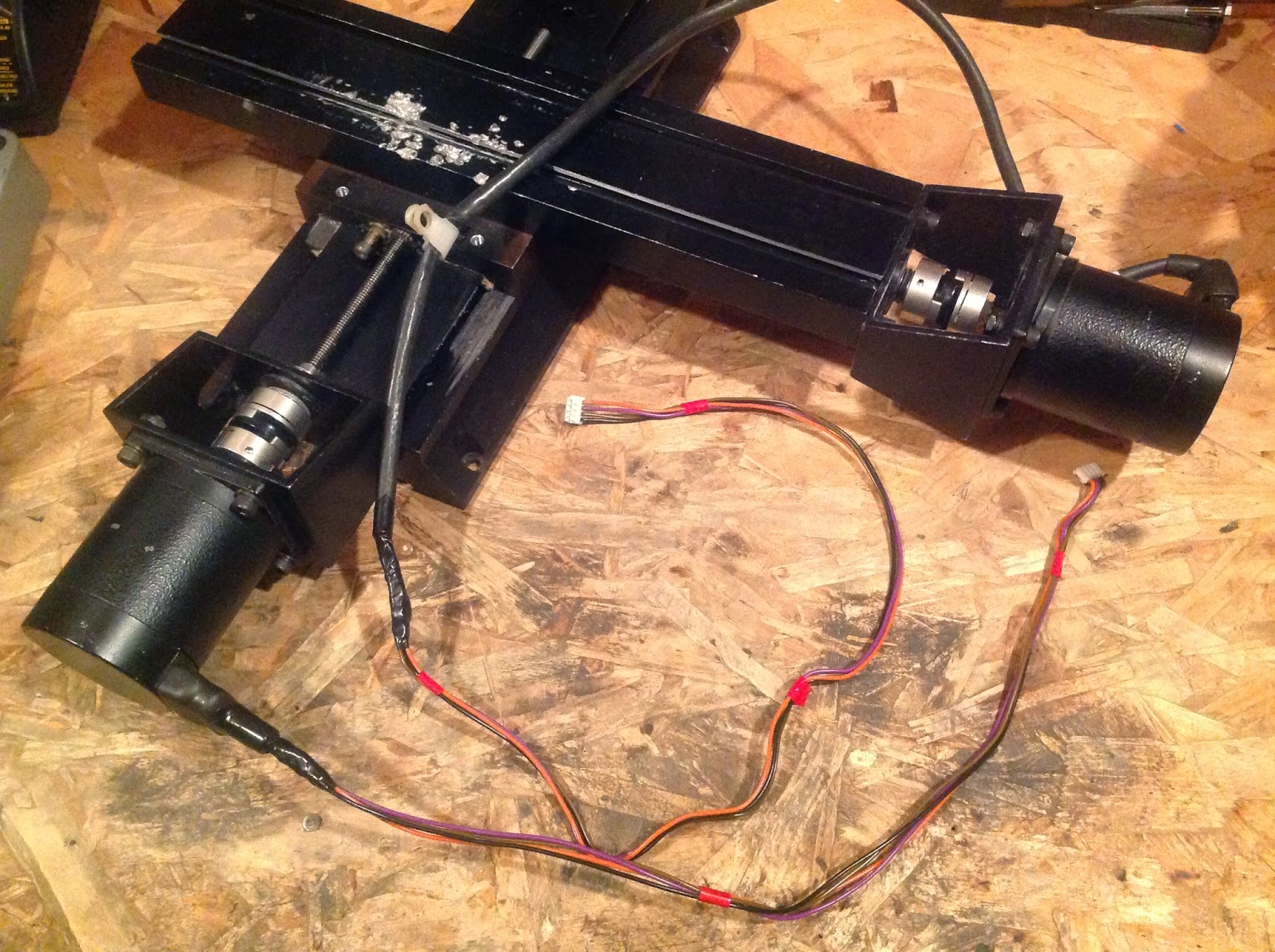
 This is the barebones XY table from an old CNC machine with an outdated control system. Without the control system, it is useless, so my robotics team took a few apart and I walked out with this! It has two giant 4-wire stepper motors, threaded rod drive, and a very hefty construction. It weighs a lot, so it won't be tipping over any time soon! In tonnight's build session I stripped it of unnecessary junk and wiped off some accumulated grease.
 These are a part of the control electronics I will be using. They are EasyDriver stepper motor controllers, graciously given to me by a friend on my robotics team. They came without the male pin headers attached, so I had to solder them on. I was a little bit unsure of myself since it was my first time soldering to a PCB, but they turned out fine! I will be using these in conjunction with a Raspberry Pi I have & a free flatscreen monitor off Craigslist to make a fully operational laser cutting workstation.
I also salvaged a few limit switches from the decrepit CNC machine to be used for homing the XY table. To summarize the build night, I assembled my inventory of main components, cleaned up the XY table, and built the EasyDrivers.
With that said, here are the parts that got this thing started!
I also salvaged a few limit switches from the decrepit CNC machine to be used for homing the XY table. To summarize the build night, I assembled my inventory of main components, cleaned up the XY table, and built the EasyDrivers.
Experiment 25: Real Gold!
A month or so ago, I was given the opportunity to raid a pile of to-be-discarded computer parts. I went to it vigorously! I built a computer with some parts, FINALLY got DVD drives with stepper motors for my laser cutter, and stole every single stick of RAM in the pile. Why did I commit this heinous act of villany? Gold! (Also, the parts were being thrown out, so without my intervention, all the parts would have gone to some recycling corporation. Not techy, DIY or scientific.) On every stick of RAM, there is a little bit of gold in the contacts. Gold is necessary for this application instead of copper because copper oxidizes and tarnishes in air, creating a layer of unconductive compounds. This will severly hamper the job of an electrical contact. To recover the gold, I used sheet metal benders to break off all of the contacts while taking nothing else. Then, I put them in a bath of copper etchant to remove the copper backing on the gold. I used NurdRage's 10:1 ratio of 3% hydrogen peroxide to 96% sulfuric acid.
 After 24 hours, I removed the solution through filtration and rinsed off all the gold flakes plastered to the contact strips. The strips still had a lot of gold on them, though, so I put them in a second round of etchant. After another 24 hours, I had removed all the gold, so I washed it and filtered it out of the spend solution, which was neutralized with baking soda until it stopped fizzing. I heated the wet gold to remove all the water sticking it together and then weighed it. Since I currently don't have access to a scale with a precision of over 1g, the gold weighed in at 0g. Sad, but I still have some cool gold. I am amazed day by day by its shininess and amazing golden color, so I would consider this experiment a "golden" success.


Experiment 24: Gallium & Coins
A while ago, I carved a template pirate booty coin from some thin plywood using my woodcarving knife. Recently, I got gallium metal (wahoo!), so I decided to make a mold for the wooden template. I used plaster of paris and just poured it over the coin in a cardboard tube. After it had dried, I pried the wood coin out. It broke the mold a bit, so I had to do surgery with epoxy and superglue. Then, I melted the gallium in a double-boiler setup over my hotplate. I have found that the gallium tends to get a layer of slag on top if it is submerged in water. The gallium cast very easily when molten and stayed molten... and stayed... and stayed. Turns out, gallium has a (very strong) tendency to supercool, which means that the liquid will cool to below its melting point of 85°F and still be liquid. This property can be great, but it is very annoying if your gallium coin never freezes. To remedy the problem, I added a crystal of solid gallium. This seed crystal jumpstarted the freezing process and in a reasonable amount of time, the gallium froze. When tried to remove it from the clutches (notice foreshadowing) of the mold, the mold flatly refused to let go. In the end, the mold broke completely and the gallium pirate booty coin turned out great! I am very pleased with how the design turned out. Sadly, the coin met its end in a hot car on a sunny summer day (it was "experimentation"), but I plan to resurrect the pirate booty coins by making a new mold and being more careful.


Experiment 23: Fashion and Printer Ink

considerably. Don't wear them in the rain!
Experiment 22: Cast Primative Slingshot Ammo
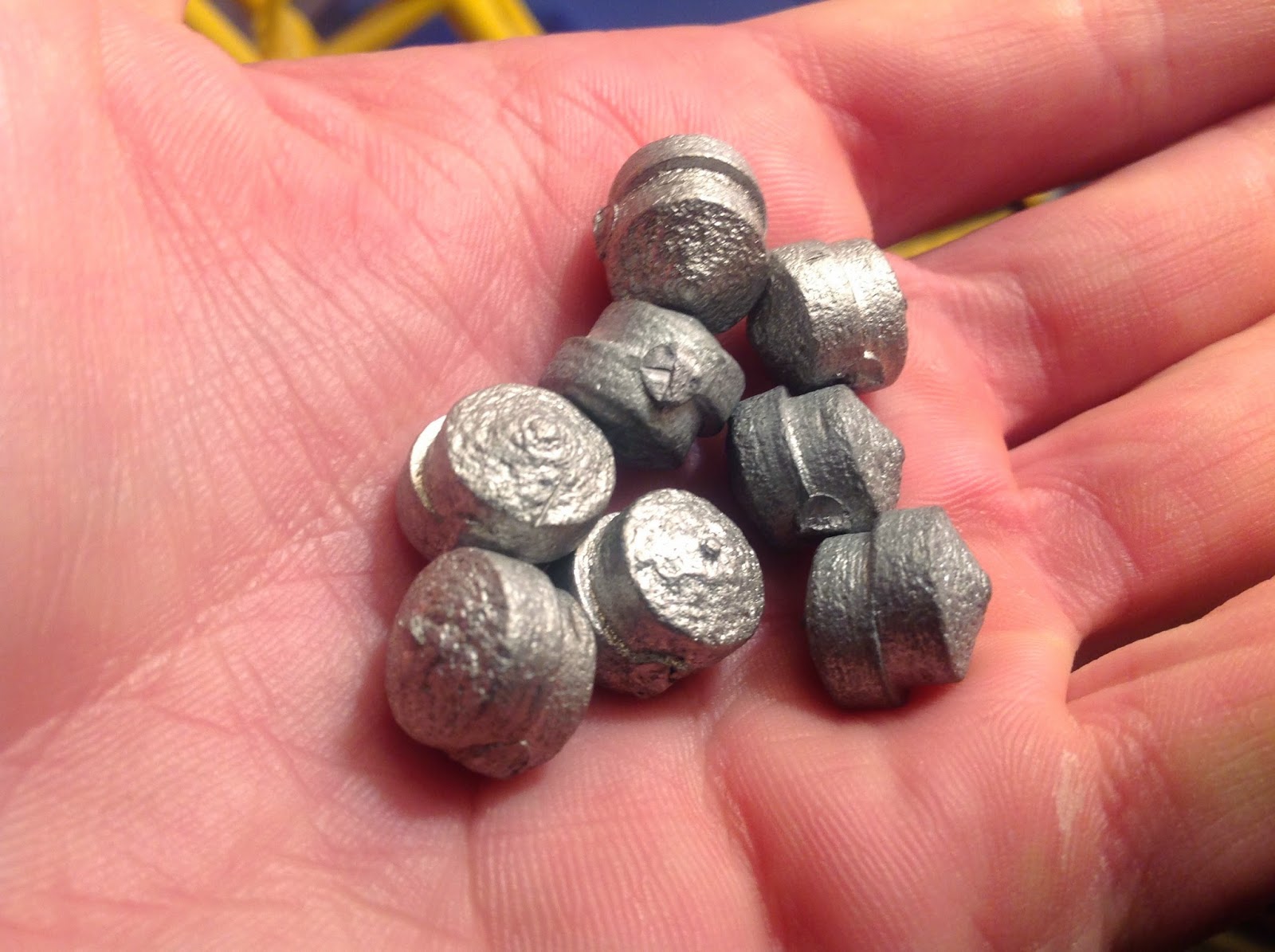
Recently, I have been quite fascinated with slingshots. They are so simple and yet, as seen on The Slingshot Channel, they are powerful beyond belief. Slingshots perform very well with lead balls or steel ball bearings for ammunition. I have none of the former and the latter are quite expensive. Thus, decided to make my own ammo! I used a drill press and some medium-density fiberboard to make a mold with two wooden dowels as a locking mechanism. it is pretty amazing what one can do with just a drill press. Then, I melted some of the same tin/lead/zinc alloy used in my Instructable from Experiment 19: Lost Wax Casting using the stove as a heat source and a tin can as a crucible. I also clamped the mold together with two woodworking clamps. It cast beautifully! The ammo aren't perfect spheres (due to drill bit shape and misalignment), but the alloy was soft, so I was able to cut off the sprue (seen in bottom left picture) with a pair of wire-cutters. After a few minutes, I was able to crank out eight really awesome slingshot balls! If I could get my hands on some pure lead, I could also make even denser, higher-performance ammunition, but I suppose these are cool enough for now. :)


Experiment 21: Sulfur Casting
After seeing Theodore Gray's sulfur fish casting, I decided that I wanted to try sulfur casting, too. Since sulfur melts at 240°F, it can be easily melted with a stove, campfire, or hot plate. I had previously tried melting the sulfur (I used plain garden sulfur) over the exhaust flame from my large aluminum furnace, but I overheated the sulfur a lot and it turned into some sort of tar substance. For my next attempt, I melted it using my hot plate (WAY less heat) with a tin can crucible (middle picture) and poured it into another tin can. It made a nice-looking disk with fascinating crystals visible on the surface. This has since broken, but I thought it was interesting enough to land it a spot in my element collection (I will be making a page about that shortly), Later, I also cast a sulfur cube using a wood fire for heat and a 1" section of aluminum box tube for a mold. When I poured the left-over molten sulfur into the fire, the liquid (which glows a dull red) caught fire and streamed into the flames with the coolest blue flame I have ever seen. I thought the sulfur looked amazing, a thin stream glowing both red and blue at the same time. In conclusion, sulfur is quite easy to melt and is amazingly fun to cast.


YouTube Account Suspension
To all my blog readers and excited fans:
Recently, I was shocked to learn that my YouTube page had been suspended, apparently for spam, scams, or deceptive content. This was strange, because I had familiarized myself with the Community Guidelines and honestly believed that I was following them. I believe I never did anything wrong. A week before the suspension, my account was in good standing, with a green circle.
As you all know, I don't post anything wrong or try to cheat the system with artificial likes or views. No spam, no scam, everything is legit. You have seen my cool metal-casting and science videos.
In other words, I feel that my account has been mistakenly and unjustly terminated. You have seen the respectful nature of this post and of all the stuff I do; if you feel the same way about my account suspension and want to continue to see all the cool projects I've got cooking up, leave a comment below expressing your support. My channel means a lot to me, to you, and to the general infrastructure I use to get my projects out there (this blog, Instructables, etc.).
Channel located at: http://www.youtube.com/user/sciencewithscreens
Yours respectfully,
ScienceWithScreens
Subscribe to:
Posts (Atom)