Coil_1A Coil_1B Coil_2A Coil_2B
but the couldn't go like:
Coil_1A Coil_2B Coil_2A Coil_1B
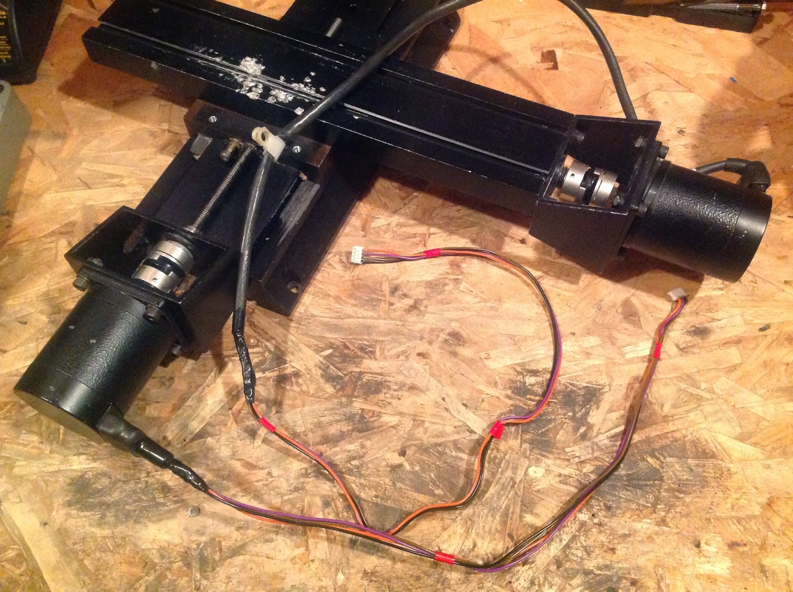
because the leads for the coils aren't together. If I wish to change the direction the stepper spins in, I can just flip the 4-pin connector 180°. Below (right) is the finished motor connection layout:

On the left are the cables to go from the EasyDriver GND-STEP-DIRECTION header to the Raspberry Pi. They are simple 3-pin connectors soldered to three solid-core breadboard-size wires for easy insertion into a breadboard. They will ultimately be soldered to all the other necessary components.
Lastly, I discovered that I need to set the EasyDrivers to accept 3.3V logic signals from the Raspberry Pi instead of their default, 5V. To set this, I simply placed a dab of solder over the solder bridge SJ2 (bottom left on boards):

I would rate the build night "highly successful." I am excited to finish the electronics tomorrow night as well as getting the Raspberry Pi up and running with code!