Experiment 10: Silver Pennies by Electrochemistry

So I saw some little kid on YouTube trying to explain how to electroplate pennies with zinc, but he was probably six years old and really didn't go into detail about what to do.  I had seen the silver & gold pennies experiment with zinc sulfate, but since I didn't have zinc sulfate or the stuff to make it, I decided to wing it.  I first placed some zinc metal I smelted out of pennies into a jar of vinegar and left it overnight to dissolve into zinc acetate.  It was probably about a 1/2 cup of vinegar.  On looking back, overnight was too long and made the solution too concentrated, so maybe leave yours dissolving for 4 hours.  When doing the electrochemistry, you do not want a very concentrated solution, or else crystals will grow instead of a nice atom-thin coating.  Anyhow, after I had the zinc acetate solution, I buffed a penny with a wire buffing wheel and a Dremel tool.  This cleans off the gunk.  After that, I cleaned it with alcohol to take off grease and other minor impurities that might interfere with the electroplating process.  Next, I used the 3.3V line on my lab power supply and hooked up the penny to the negative lead and a piece of zinc metal on the positive lead.  I placed them both in the zinc acetate solution, making sure that the negative lead was submerged and the positive lead was not.  If the positive lead is in the solution (instead of just the zinc metal) it can corrode.  After rotating the penny a few times, I had a very good plating of zinc.
I noticed that the plating was not very shiny, so I buffed it with the metal brush Dremel buffing wheel.  It turned out absolutely amazing!  Here are pictures of the finished penny (the images do little justice to how nice the penny really looks).

Experiment 9: Hydrogen Balloon Explosion

I find hydrogen and oxygen interesting, especially when they combust.  In this experiment, I ignited a balloon filled with pure hydrogen gas.  To make the gas, I placed 0.6 grams of magnesium powder in a balloon and then placed the balloon on the top of an Erlenmeyer flask filled with 50 mL of 1.0 molar hydrochloric acid.  When I tipped the balloon to allow the magnesium powder to contact the acid, the reactants reacted to form magnesium chloride and hydrogen gas.  Since the reaction is exothermic, it grew quite warm.  After I tied the balloon off, I taped a candle to a yardstick and lit the candle.  If you want more gas, and thus more fun and danger (whee!), you should use more acid and more magnesium.  In this video I show the results, using my lit candle to ignite my very awesome gas:

Experiment 8: Electrolytic Rust Removal

Electrolytic rust removal is very helpful for removing rust from ferrous objects, as it does not damage the underlying metal and is quite a good "lazy" method.  I had some rusty railroad spikes (no, I did not steal them from an active railroad - October Sky), so I tried this method on them using my lab power supply from Experiment 7: ATX Computer Power Supply Conversion.  To actually remove the rust from the spikes, I poured one gallon of water and one tablespoon of washing soda (not baking soda or baking powder) into a bucket and stirred.  For my anode, which connected to the +12V terminal and is eventually eroded away, I used a flattened out wall of a steel soup can.  The cathode, which the rust is removed from, was obviously my railroad spike.  After I connected the +12V and GROUND terminals, I made sure that the leads got good connections to the electrodes by testing for a voltage drop with my voltmeter.  The voltage should drop if the electrolysis is actually running.  Every so often I turned the spike around to ensure that the anode had a good "line of sight" to all the surfaces.  Note that while it is fine for the black GROUND wire to be submerged, you will destroy your positive lead if you submerge it.  Once I saw that all the corrosion on the spike had turned black, I took it out of the bucket and scrubbed it off with a bristle brush.  After that, I washed it with hot water to warm the piece, and after drying it with towel, let the stored heat dry off the residual water.  I got some very nice results, so here are the before and after pictures:

Experiment 7: ATX Computer Power Supply Conversion

As I said before, I purchased an ATX power supply unit for 
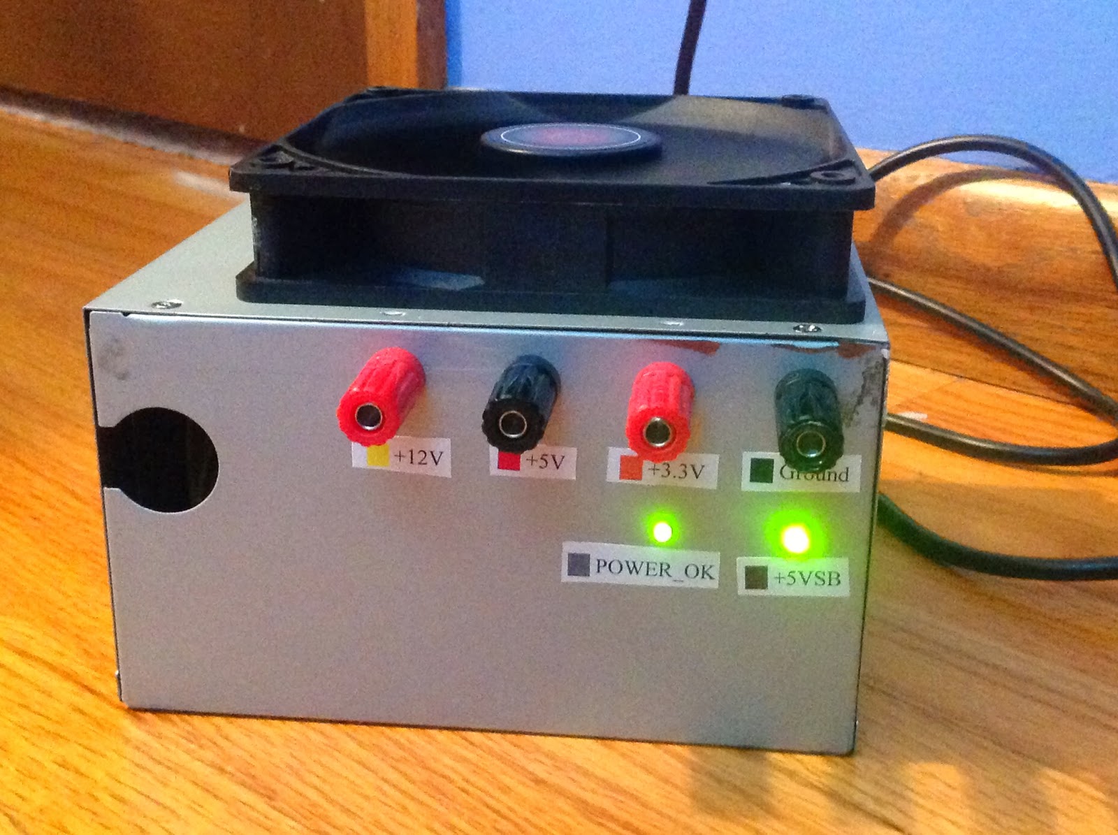
Experiment 1: Hard Drive Sander.  I have been in need of a good lab power supply for multiple experiments, so I decided to modify that computer power supply to make it into a lab power supply.  First, I unscrewed the case and unplugged the fan connector from the PCB inside to give better access to all the wires.  Then, I chopped off all the computer connectors at the ends of the wires and grouped the wires all together by color.  I drilled some holes for binding posts in the side of the PSU and two more holes for LEDs.  After I installed the binding posts, I soldered all the black (ground) wires to one post, all the orange (3.3V) wires to another, all the red (5V) wires to another, and all the yellow (12V) wires to yet another binding post.  Having done so, I connected the green wire, which normally goes to the front switch on a computer, to the ground so that the power supply would power on when I flipped the switch at the back.  The green wire must be connected to the black to turn on the PSU.  Also, the brown 3.3V sense wire must be connected to the orange 3.3V terminal.  My supply had a blue -12V wire and a white -5V wire, but the binding posts I used were ridiculously expensive, so I opted to not connect those wires to binding posts and ended up leaving them inside the supply.  I hooked up the purple (+5VSB) wire to an LED and then to ground using a 330 Ohm resistor in the middle.  The purple wire outputs +5V if the power supply is switched on and connected to an outlet.  My last connection was the grey (POWER_OK) wire to an LED and ground with another 330 Ohm resistor.  The POWER_OK signal is low, or off, if the supply begins to give bad voltages.  That way computer processors can turn off before they are damaged by incorrect voltages.  I basically used the +5VSB and POWER_OK LEDs to show me if the supply was connected and on, and if it was supplying the correct voltages.  To finish everything off, I plugged in the fan connector again and the screwed the supply's lid back on, this time leaving the fan on top of the case because there was no space inside.  I measured the voltages and everything was correct and stable to +/- 0.01V, so the modification passed! I later added nice labels.  Here is the finished lab power supply: