While I didn't succeed in extracting manganese metal, I certainly got my money's worth of fiery, beautiful thermite! After some online research, it appears that battery paste has a lot of carbon, which would definitely hurt a thermite reaction by throwing off the stoichiometry and absorbing heat. In the future, I may try purifying battery paste or I may use pottery manganese dioxide in my thermite. The third time's the charm!
Experiment 46: Manganese Dioxide Thermite
I wanted manganese metal for my element collection, so I tried a thermite reaction to extract it from manganese dioxide. Really, I just like thermite in general, so any oxides I can get my hands on are susceptible to being reduced. :) To get my manganese dioxide, I removed the black electrolyte sludge from alkaline and dry cell batteries. Then, I washed the paste, dried it in the oven, and ball milled it to a fine powder. I mixed this with some of my ball-milled aluminum powder in a 2.42:1 MnO2:Al ratio and placed it in a flowerpot for ignition.
Ignition was accomplished with a magnesium ribbon, and the reaction proceeded, but not as vigorously as I had expected. Whereas the thermite should have burnt itself out in less than 30 seconds, mine took over two minutes to finish. The slag was a crumbly, dirt-like powder, instead of the molten glass and metal that should have appeared. I thought that my aluminum powder wasn't fine enough, so I ran my ball mill for a longer time and tried again, but the thermite still didn't produce any lumps of manganese metal. However, the slag powder stuck to a magnet, which could indicate that it has metallic manganese or a manganese alloy in the slag.
While I didn't succeed in extracting manganese metal, I certainly got my money's worth of fiery, beautiful thermite! After some online research, it appears that battery paste has a lot of carbon, which would definitely hurt a thermite reaction by throwing off the stoichiometry and absorbing heat. In the future, I may try purifying battery paste or I may use pottery manganese dioxide in my thermite. The third time's the charm!
While I didn't succeed in extracting manganese metal, I certainly got my money's worth of fiery, beautiful thermite! After some online research, it appears that battery paste has a lot of carbon, which would definitely hurt a thermite reaction by throwing off the stoichiometry and absorbing heat. In the future, I may try purifying battery paste or I may use pottery manganese dioxide in my thermite. The third time's the charm!
Experiment 45: Lithium Metal from Coin Cells
A very long time ago, in Experiment 2: Lithium Battery, I extracted lithium foil from some old lithium cordless phone batteries. The batteries were constructed similarly to AA batteries, with a cathode and an anode wrapped up in a very tight roll. While fun to play with, the lithium from the batteries oxidized quickly and was really hard to store well. I wanted some shiny lithium and had some "2032" coin cell batteries, so I decided to extract the lithium from them.
 For this experiment, fresh batteries are crucial. If the battery voltage is much less than 3V, the lithium inside will be corroded unrecognizably. I practiced my battery-opening skills on a dead coin cell and used side cutters to twist the cathode rim away from the anode cup. I then pried the anode cup out and removed the paper separator to get to where the lithium would have been had the battery not been dead. When dealing with lithium, speed is important because exposure to moist air will oxidize and darken the lithium, which makes it less appealing than shiny metal.
 Once I practiced my technique, I rapidly disassembled three fresh lithium coin cells and scraped the lithium off of the anode cup into a beaker of mineral oil. I was impressed by the amount of lithium inside such a tiny battery. With the lithium temporarily protected from the atmosphere in the oil, I submerged a small sample vial in the oil and flicked all the bubbles off of its sides. After the vial and its lid were free of air, I coerced all my lithium shavings into entering the container. This was especially tricky because lithium is lighter than oil and wants to float. In the end, however, I got all of the lithium into the vial.

To finish up, I let the lithium react with whatever was in the mineral oil and then carefully tipped the vial just a bit to let the small gas bubble escape. I capped the vial tightly (while still under mineral oil) and then dried it off with a paper towel. Even weeks after the extraction, the lithium metal is still shiny where fresh surfaces were exposed during the scraping. The sample is a nicely dangerous and beautiful addition to my element collection.
 For this experiment, fresh batteries are crucial. If the battery voltage is much less than 3V, the lithium inside will be corroded unrecognizably. I practiced my battery-opening skills on a dead coin cell and used side cutters to twist the cathode rim away from the anode cup. I then pried the anode cup out and removed the paper separator to get to where the lithium would have been had the battery not been dead. When dealing with lithium, speed is important because exposure to moist air will oxidize and darken the lithium, which makes it less appealing than shiny metal.

To finish up, I let the lithium react with whatever was in the mineral oil and then carefully tipped the vial just a bit to let the small gas bubble escape. I capped the vial tightly (while still under mineral oil) and then dried it off with a paper towel. Even weeks after the extraction, the lithium metal is still shiny where fresh surfaces were exposed during the scraping. The sample is a nicely dangerous and beautiful addition to my element collection.
Experiment 44: Nickel Acetate and Nickel Electroplating
 I thought it would be fun to try electroplating with nickel, since nickel has a fancy golden-silvery hue and doesn't tarnish easily. To start, I followed this Instructable to make a dilute solution of nickel acetate. In summary, nickel metal is electrolyzed in a solution of vinegar and salt using 12V. I used two Canadian nickels and my ATX lab power supply's 12V. Some Canadian quarters, dimes, and nickes are pure nickel; check with Wikipedia to see if the coin's year means it is nickel or not. I let my coins dissolve until the solution was a nice bright green color. Once the nickel acetate electroplating bath was done, I moved on to the fun part--electroplating!
To prepare my copper pennies for electroplating, I first dipped them in dilute sulfuric acid and then in a sodium hydroxide solution. The acid removes some surface contaminants and the base removes others. A very clean surface is necessary for a good, solid plating. Once the pennies were clean, I attached them to the negative clip of a 3V AA battery pack. For nickel plating, lower voltages are usually better, and lower amperages also help with smooth finishes. Thus, batteries at low voltage and low current are better than, say, an ATX 12V line. The anode, or positive terminal, of the plating bath was a nickel coin. It is important to note that the anode alligator clip should be above the water line or else it will be corroded away along with the nickel coin.
 With the penny in the solution, I rotated it every thirty seconds to give it an even plating. After about a minute, I moved the battery pack alligator clip to a new position on the coin so that every area was plated. Once I had plated the coin for about three minutes, I washed it off and it was brilliantly shiny!
The coins didn't need any polishing at all, which I thought was really cool--my experiments with zinc plating were never this shiny. When compared with the blue-tinted zinc-plated coins I already had, the nickel-plated ones had a very beautiful golden-silver tint. I also plated steel with success by washing it in the acid and base and then repeating the plating procedure.
After I was done electroplating, I evaporated the nickel acetate plating solution by letting it sit uncovered for a month or so. This made some really nice chips of bright aqua nickel acetate crystals. I also made copper acetate by the same electrolysis method, and that evaporated down into very dark green kite-shaped crystals.

Experiment 43: Isolating Red Phosphorus from Matchbooks
Phosphorus! The word brings to mind war, fire, and Thomas Edison. In all of these cases, phosphorus is memorable for its dangerous properties. Specifically, the allotrope white phosphorus autoignites in air and burns, spraying toxic droplets of white phosphorus everywhere. Its less-dangerous brother, red phosphorus, can be found in nearly every home.
I wanted some phosphorus for my element collection, so I chose red phosphorus over the extremely deadly white phosphorus. Red phosphorus (with crushed glass) is on the dark red striker pads on boxes of matches, so I collected 14 of these and cut off the striker pads. I placed these into acetone to dissolve the glue binding the red phosphorus to the cardboard. This went rather quickly, and after some stirring to dislodge any remaining red phosphorus, I removed each soggy strip of cardboard and washed it with more acetone. This helped catch any remaining red phosphorus and reduce losses. There isn't much red phosphorus on each strip to begin with, so careful handling is critical in this experiment.
After I had collected all the red phosphorus in the acetone, I let the mixture settle and then decanted off most of the acetone. I let the rest evaporate outside. To purify the red phosphorus from the annoying fibers of cardboard in the matted red cake, I poured in some concentrated sulfuric acid and heated the mixture outside on a hotplate. Needless to say, this step is dangerous and personal protective equipment is absolutely necessary. The hot sulfuric acid will release fumes as it chars the paper bits into carbon powder, so be mindful of that if you do this experiment yourself. Additionally, the mixture may "burp" a little, so a watch glass over the beaker might be helpful keeping the acid in the beaker.
 Once I was satisfied that all the paper had been completely destroyed, I let the mix cool and placed the beaker in cold water. Then, I carefully added cold water to the beaker's contents, drop by drop, until I filled it to the top. This must be done slowly, as the dissolution of sulfuric acid into water releases a lot of heat. I let the mixture settle and decanted off the top portion of water. Then, I diluted and decanted the mix six more times so that no sulfuric acid remained in the beaker. Finally, I let the remaining water evaporate and then scraped the purified red phosphorus onto a sheet of paper.
To finish the experiment, I made another glass ampoule (Experiment 28: DIY scientific ampoules) and mushed the rounded base of the test tube into a flat bottom so the ampoule could stand upright. I then carefully tapped the red phosphorus powder into the amoule and sealed it with a torch (I first cleaned all residue off the neck of the ampoule). The resulting red powder is a pretty color and makes a very interesting sample for my collection.
Experiment 42: Extracting Tantalum Metal from Capacitors
After reading some interesting notes on another chemistry blog, I found out that there was solid tantalum metal inside tantalum capacitors. Apparently, tantalum is comparable in price to gold, but I wanted the tantalum for my element collection, not for scrap value. Intrigued, I rummaged through my mountainous stack of scrap circuit boards to find all their tantalum capacitors.
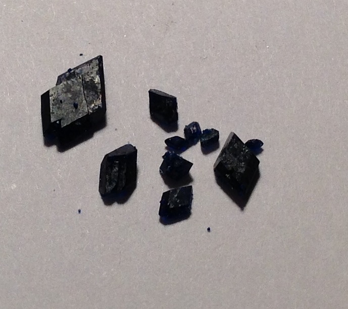
 I found around thirty tantalum caps on different boards and broke them off. They are somewhat distinctive in appearance, but a Google search for "tantalum capacitor" also helped with identification. The tantalum capacitors I got can be seen in the picture on the right.
To extract the tantalum, I used a hammer to lightly tap on the larger capacitors and used pliers to crush the epoxy on the smaller ones. The tantalum inside is a somewhat-fragile sintered block, so don't go crazy wacking them, or they will break. Each tantalum block had a small tantalum wire attached to it, and this wire was attached to the capacitor SMD solder pad. I removed the solder pads from all the blocks I broke out of the epoxy and then placed the tantalum into a test tube for further cleaning. I added sand and water to the test tube and shook it vigorously to abrade off the manganese dioxide electrolyte on the surface of the tantalum.
 Once the tantalum was clean and dry, I ended up with twenty-five miniscule black tantalum blocks with anodized tantalum wires protruding from them. I thought they were pretty neat, since they were quite heavy for their size, owing to tantalums density of ~16g/cc. The wire anodization colors were also interesting and ranged from blue to green. They weighed just about one gram total and made a really fascinating sample for my element collection. Who knew tantalum was in every computer?
Experiment 41: Growing Sulfur Crystals


Then, with my solvent collected, I began the recrystallization. I placed the xylene in a beaker with a stir bar and some impure sulfur and heated it on medium heat on my hotplate. I also had a beaker full of snow water resting on top of the xylene beaker to act as a crude condenser and recover xylene vapors. The whole experiment was done outside. The xylene shouldn't boil, or else vapors will go everywhere and escape the crude condenser setup in large quantities (unhealthy).
With the sulfur dissolving, I placed another beaker with a small amount of xylene (no sulfur) on the hotplate to warm. I also put a third clean beaker on the hotplate with a coffee filter on its top. Just as the xylene began to boil, I poured the prewarmed pure xylene through the filter in the third beaker. This warmed the filter and the beaker to prevent sulfur from crystallizing immediately on contact with the cold surfaces. Then, I filtered the dissolved sulfur mixture through the filter.
 Once it finished filtering, I removed the filter and covered the beaker's mouth with tape to prevent losing xylene vapors. I then wrapped the hot beaker in towels to slow its cooling. This helped the crystals to grow more slowly, which makes bigger crystals. Once it cooled completely, I decanted off the xylene (which still had some dissolved sulfur in it) and scraped the sulfur crystals onto a coffee filter to dry. After the first batch was dry, I tried using them as seed crystals for a second and third batch of crystals, which seemed to make larger, prettier crystals. The resulting pure, shiny piles of sulfur crystals were quite beautiful.
Experiment 40: Glowing Xenon Plasma Tubes!
This experiment came about completely by chance. When playing with my Whimshurst machine from Experiment 30: Miniature Wimshurst Machine and the small xenon flash tubes from the disposable cameras I disassembled in Experiment 39: Electromagnetic Coilgun, I discovered that the static electricity made an extremely brief flash in the tube. Intrigued, I connected the flash tube to a 10Mohm ballasted high voltage power supply and discovered that the tube lit up! The xenon stayed excited and hosted weird bouncing blue-white arcs! I was amazed! After quite extensive experimentation, I observed some interesting behaviors. For example, when connected in series with a small arc gap, the xenon tube's jagged, jiggling arcs changed to a single soft, stationary arc. I also noticed that touching the outside of the glass tube with a bare finger caused the arcs inside to become smaller and more numerous, as well as more active in their bouncing. After a while, I decided to make a light-up periodic table specimen of xenon. I had to get another high voltage supply since the one I originally used was for another project, so I used the CCFL inverter from an old LCD monitor.
 After removing the cover of the monitor, I turned it on and probed the inverter board with my multimeter (I identified it based on its "WARNING: High Voltage" label). I gathered enough information from the voltage readings of the input of the board to identify +12V and GND. A search of the part number online turned up a datasheet which identified the dimming (0-5V) and on/off (+3V/0V) pins. Using my ATX lab power supply, I was able to make the fluorescent tube of the monitor turn on at my command. I used a LM317 voltage regulator circuit to provide a variable voltage to the dimming pin, which controls the current flow and thus the lamp brightness. I then connected my xenon tube between one of the high voltage outputs and the return on the inverter and tested the setup. It worked! With more current, the xenon tube's sharp, jagged arcs changed to an odd sine wave shape with smoother corners. This made the tube run hot, though, so I ended up using a lower current setting.
During this process, I accidentally discovered that holding a neon or xenon bulb (finger touching glass) near the high voltage caused an arc to jump from the high voltage wire to the electrode of the tube and also made a soft, pleasant glow inside the tube. I loved this effect and, after many frustrating failed attempts to reliably replicate it, found a solution. After reading up on how camera flashes work, I learned that a high positive voltage applied to the glass outside of the tube ionizes the gas inside, allowing current to flow and make the blinding white arc. I tried connecting a camera flash's ionization wire to the high voltage, and with an electrode connected to the return, I got the amazing soft glow! It wasn't very uniform, though, so I experimented more and found that connecting both electrodes to the return helped the uniformity.

To make the periodic table display, I wound a fine wire around one of my smaller xenon tubes and epoxied the ends in place. This was my ionization electrode. I cut a small wood base to fit in my periodic table and made some copper frame wires to hold three xenon tubes in place. Then, I soldered one large xenon tube to be in an arcing configuration and two other tubes to be in an ionized glow configuration. These I connected to the inverter so that the glowing tubes shared one high voltage output and the arcing tube got an output to itself. Since my periodic table wasn't near any outlets, I used eight AA batteries in two 4xAA packs to power the inveter and LM317. After installation, I was extremely happy with the blue-white light emanating from my Xe periodic table cubby. Though the project took a long time to complete, I am glad I saw it through. Noble gases are pretty, aren't they?
Experiment 39: Electromagnetic Coilgun!
Like the ball mill, this is another project I've been working on for some time. After being inspired by a friend, I decided that I absolutely had to have one of these delightful toys. In principle, a coilgun works by using a coil (duh!) to create a strong magnetic field which pulls a ferrous projectile forward. As the projectile enters the center of the coil windings, the coil turns off, releasing the projectile on its deadly flight.
To store the energy for the intense magnetic field, I used 17 disposable camera capacitors arranged in parallel. These capacitors are charged by four identical camera capacitor charger circuits whose outputs are wired in parallel to the capacitor bank. The inputs to the chargers are wired in parallel to a normal-duty switch, which connects the charger inputs to four AA batteries, also in parallel. All this parallel-ness makes the capacitors charge faster and lets them dump more power all at once into the coil.
The "trigger" for this coilgun is a heavy-duty (20 amp/250VAC) switch wired between the coil and the capacitor bank. While this setup works decently well, I have noticed that the switch contacts occasionally weld themselves together from the massive (possibly lethal) amounts of electricity being flung across them. I may fix this at a later date with a better solution.
To make the coil, I took ~90 feet of 30AWG wire from a microwave oven transformer secondary/high voltage winding. I cut this in half and twisted the ends together to make two strands in parallel. I then wound this around a pen tube with two acrylic end stops 30mm apart from each other. I did 10 layers this way before sealing the wires tightly in place with hot glue. The coil began 30mm from the frontmost part of the end cap of the pen.
The projectiles I am using are 30mm sections of 1/4-20 bolts and 30mm sections of 6mm steel rod. They work really well and are cheap. I placed some of them in a copper sulfate bath (after a brief cleaning dip in 25% H2SO4 and then in aqueous NaOH) and then polished them to give them a shiny copper plating, which adds to the "authentic bullet look."
As you can see from the video, it's a pretty fun toy! To wrap up the project, I did a test measuring the projectile drop in altitude versus the distance of the shot to calculate the muzzle velocity. As it turns out, this gun has a 12 m/s muzzle velocity with a 7g steel bullet. The bullet then has a kinetic energy of 0.5 joule. *Sigh* Ah - it's still fun even if it's weaker than a BB gun.
Experiment 38: Iron Thermite!
After years of anticipation, I finally succeeded in making iron thermite, the king of infernos! I used the aluminum powder from Experiment 35: Ball Mill & Aluminum Powder for Thermite and the iron (III) oxide from Experiment 37: Making Iron (III) Oxide for Thermite mixed intimately in a 1:3 mass ratio. The resulting mixture was a somewhat golden color and had the consistency of flour. I placed the powder in a depression dug in a pan of sand and lit it with a 2" magnesium ribbon. The reaction exceeded my wildest expectations - it was an utterly brilliant ball of orange flame, totally engulfing the pan with its furious power. Check out the video below for footage of the event:
 After the slag cooled, I removed it from the sand and broke it into fine pieces using a hammer. For the most part, it was bubble-filled glassy alumina that easily fractured. In some pieces, I found small blobs of iron produced by the reaction. I cleaned the black oxide off the pieces of iron using vinegar and then swished them around with sand to abrade off other surface contaminants. After weight the resulting product, I was absolutely astonished to find out that I had only recovered 16 grams of iron from the reaction! Without even calculating anything, that is a terrible yield, considering I converted over 200 grams of iron in my iron (III) oxid
e producttion. But since I like chemistry, I did some simple stoichiometry to reveal that starting with 322 grams iron (III) oxide, the theoretical yield would be 225 grams iron metal, so I got a 7% yield. I believe most of my iron flew up during the reaction and rained down to earth as tiny iron droplets. Honestly, though, the yield is of little concern to me considering how exciting the reaction was. :)
Also, I have now started a Summer of Thermite playlist on YouTube, so be sure to subscribe to my blog by email or to my channel via YouTube to keep up with these firey experiments. I plan on doing many more reactions similar to this one.
 After the slag cooled, I removed it from the sand and broke it into fine pieces using a hammer. For the most part, it was bubble-filled glassy alumina that easily fractured. In some pieces, I found small blobs of iron produced by the reaction. I cleaned the black oxide off the pieces of iron using vinegar and then swished them around with sand to abrade off other surface contaminants. After weight the resulting product, I was absolutely astonished to find out that I had only recovered 16 grams of iron from the reaction! Without even calculating anything, that is a terrible yield, considering I converted over 200 grams of iron in my iron (III) oxid
e producttion. But since I like chemistry, I did some simple stoichiometry to reveal that starting with 322 grams iron (III) oxide, the theoretical yield would be 225 grams iron metal, so I got a 7% yield. I believe most of my iron flew up during the reaction and rained down to earth as tiny iron droplets. Honestly, though, the yield is of little concern to me considering how exciting the reaction was. :)
Experiment 37: Making Iron (III) Oxide for Thermite
In the last experiment, I made fine aluminum powder, with the intention of doing the thermite reaction. The most common type of thermite is the iron thermite, and its second ingredient is iron oxide. Both red and black iron oxide will work, but I used red (iron (III) oxide), because it was the most common and I saw good instructions on making it. Basically, the process involves running electricity through iron electrodes in a brine electrolyte until one electrode is completely eroded away. This produces rust from the iron. I switched the polarity (+12V and ground) of my electrodes every 12 hours to even out the erosion and make the cell last longer. After 36 hours, I drained the excess water and baked the sludge at 400°F for an hour. I then ball milled the product to a fine powder. I also made a video showing the system I developed of making red iron oxide in large amounts (it works quite well):
Update to Experiment 7: ATX Computer Power Supply Conversion
Although blowing up hydroxy-filled bags and creating shotgun-level bangs was fun, the end result of the last experiment was that I burnt out my lab power supply. To remedy this situation, I acquired another ATX PSU from a friend and converted it, this time with some added flair.

I had also previously broken a blade of the fan on my lab power supply. The fan was on top as there was no space left inside the unit. However, I didn't have extra screws for the fan cover, so I left it off, and a fan blade got broken. For my second lab power supply, I reused four screws from the broken unit to attach the fan cover, which gave the supply a nice shiny finish.
Previously, I used two packs of overpriced binding posts from RadioShack. Each pack had one red and one black, which meant that for three positive voltages I either had to buy even three packs or just use a black post where a red one should have gone. I opted to use a black binding post where a red one should have gone in the +5V terminal. That didn't look good, so this time around I found an online supplier and exactly what I needed.

I had also previously broken a blade of the fan on my lab power supply. The fan was on top as there was no space left inside the unit. However, I didn't have extra screws for the fan cover, so I left it off, and a fan blade got broken. For my second lab power supply, I reused four screws from the broken unit to attach the fan cover, which gave the supply a nice shiny finish.
Lessons learned from destroying and rebuilding my lab PSU:
- Don't try to trick the overcurrent protection on an ATX PSU - it's there for a reason.
- Source parts online - it's cheaper (sometimes free) and has better selection that RadioShack.
- Using social connections to obtain unwanted (but useful) parts can pay off handsomely - the PSU I previously bought for $20 was free the second time around.
Experiment 36: Hydroxy Gas Fun
A very, very long time ago, I found a cool YouTube video (this is how everything starts, right?) showing a hydroxy torch melting stuff. Hydroxy torches are pretty neat, because they burn H2 and O2 gas cleanly, only producing water and a whole lot of heat. The heart of the hydroxy torch is a hydroxy generator, which electrolyzes water to split it into its constituent gases. I tried making one with hot glue and some scrap metal, and it failed about as badly as the word "hot glue" signifies. Hot glue is an inferior building material.
Years later, I was inspired to work on the project again when I saw a friend's hydroxy generator that he bought off eBay. I used the same scrap metal from the first generator design, but this time I used some proper plastic rods with spacers to assemble my electrolysis plates. This time, the design worked beautifully! I demonstrated that the generator worked by filling various containers with the explosive hydroxy gas and igniting them with a remote match. The video below has a compilation of some of the best explosions:
Regrettably, I seem to have burnt out my lab power supply (Experiment 7: ATX Computer Power Supply Conversion), so I'll have to make a new one and be more careful with my current consumption. Perhaps after that, I will use the hydroxy gas for a torch, but as of now, I am extremely happy with my newfound source of earth-shattering explosions. :)
Years later, I was inspired to work on the project again when I saw a friend's hydroxy generator that he bought off eBay. I used the same scrap metal from the first generator design, but this time I used some proper plastic rods with spacers to assemble my electrolysis plates. This time, the design worked beautifully! I demonstrated that the generator worked by filling various containers with the explosive hydroxy gas and igniting them with a remote match. The video below has a compilation of some of the best explosions:
Experiment 35: Ball Mill & Aluminum Powder for Thermite
Years and years ago, I decided I wanted to make thermite, so I tried to make a ball mill for producing aluminum powder, a key ingredient of most thermites. A ball mill powderizes materials by crushing them with the continual falling action of hard milling balls (in my case steel ball bearings). My first attempts to build a ball mill failed horribly. They were slow, finnicky, and didn't work at all. A couple months and a few YouTube videos later, I built one using a corded drill and some castor wheels, along with a metal container. The attachment of the drill to the container lid was so stressful that I ripped a perfect circle out of the container lid. I then switched to a plastic container with small bars on the inside to lift the balls up and send them crashing down on the aluminum foil inside. This worked... until the drill melted. No joke, the plastic on the drill melted and that was the end of the drill. Oops.
A few more months went by, and then I got a free dryer off Craigslist. The motor worked well, even though the first attempts to use it didn't. One time the motor spun so fast the ball mill container flew off toward the ceiling! I finally figured out a way to harness the speed of the motor with some belts and wheels to tame its ferocity. However, the ball mill still had the small bars on the inside. Most ball mills don't have these, for good reasons - they are loud and hard to clean (especially when attached with duct tape!). So, I took them off, and the balls in the mill proceeded to slide, rather than tumble. After a few more months of apathetically looking at the years-long failed project, I finally got the motivation to finish it and found a container that I hoped was the right size - the balls filled it approximately halfway up. To my extreme surprise, the ball mill worked! After years of dissapointment and failed prototypes, the mill jar finally opened to reveal ultra-fine aluminum powder! This is how many things in the inventing/experimenting business go. They take perseverance and dedication to finish and might not be immediately rewarding, but they will pay off if you finish strong and pull through until the end.
This has been the too-long story of how I built the ball mill to finally fulfill my dream of thermite. It takes about a week for it to turn foil shreds into fine powder. The aluminum powder produced has been confirmed to work in thermite. To sum up the mill's actual operation, I made the above video explaining how it works for milling aluminum... or anything else highly flammable. :)
“I have not failed. I've just found 10,000 ways that won't work.”
― Thomas A. Edison
A few more months went by, and then I got a free dryer off Craigslist. The motor worked well, even though the first attempts to use it didn't. One time the motor spun so fast the ball mill container flew off toward the ceiling! I finally figured out a way to harness the speed of the motor with some belts and wheels to tame its ferocity. However, the ball mill still had the small bars on the inside. Most ball mills don't have these, for good reasons - they are loud and hard to clean (especially when attached with duct tape!). So, I took them off, and the balls in the mill proceeded to slide, rather than tumble. After a few more months of apathetically looking at the years-long failed project, I finally got the motivation to finish it and found a container that I hoped was the right size - the balls filled it approximately halfway up. To my extreme surprise, the ball mill worked! After years of dissapointment and failed prototypes, the mill jar finally opened to reveal ultra-fine aluminum powder! This is how many things in the inventing/experimenting business go. They take perseverance and dedication to finish and might not be immediately rewarding, but they will pay off if you finish strong and pull through until the end.
“I have not failed. I've just found 10,000 ways that won't work.”
― Thomas A. Edison
Experiment 34: DIY Metal Stamping
 A while ago, I found myself wanting a good way to make metal stamps for stamping element symbols into the various pieces of metal I have, in order to identify them when the time came to melt them into new and interesting objects. To accomplish this, I used a steel bolt and the electro-etching process to make a neat little stamp for hammering into metal. I first sanded the head of a bolt so it was flat and almost mirror-like in finish. Then, I applied masking tape and used a box cutter (along with a strong light) to painstakingly cut away the design, flipped in reverse. Since it's reversed, it will stamp out in the right direction. I then attached the bolt to my power supply's +12V and hooked another wire up to the ground terminal. I then placed the ground wire in the bottom of a dish with about 1/2" of strong salt water and put a cotton ball on top of it's exposed metal strands. I pressed the bolt head onto this lightly and waited about 10 minutes. What happens is the electricity erodes the exposed areas of the positive anode, producing iron oxide. This darkens the brine solution. After about 10 minutes of etching, I rinsed off the bolt and peeled off the tape. The places under the tape were still shiny, but the exposed areas had eroded away considerably and were deeper than the lettering, as seen above.
 Finally, although it might not have been necessary, I hardened and tempered the stamp. This will prevent undue wear of the stamp, since it will undergo a lot of force throughout its life. I used a propane torch to heat the stamp head bright orange and then quickly dropped it in room-temperature water. To relieve the stresses built up by the sudden change in temperature, I tempered the stamp by heating its entirety to a blue color and then letting it cool in air. After testing on a strip of metal, I was quite pleased with the result. Honestly, I didn't think it would turn out this well.
Random Afternoon Project: The Coin Sorting Machine
This is what happens when I get bored on a summer afternoon. After being inspired by a recent Instructables project showing how to make a coin sorting machine, I built my own, changing a few things (for example, this sorts U.S. currency instead of Phillipine currency) and adding a silly name laser-engraved into the front.


The machine uses gravity and a slight backward tilt of the front window assembly to sort coins using specially-sized windows cut into the cardboard. The coins want to fall backwards, so when they get to the right window, they drop off the ramp, thus ensuring that they don't fall into a larger window farther down on the ramp.
I also engraved the name "Moolah Masta 3000" and some icons into the front of the sorter using my laser cutter. I have a category of posts related to building the laser cutter and fixing the issues that sprang up with its scavenged parts.
So far, the soin sorter hasn't every mis-sorted coins or gotten them awkwardly stuck. For having no moving parts, it works surprisingly well!
Experiment 33: Isolating Elemental Iodine
This was an especially fun experiment. After all, who can resist hand-staining chemicals that give off dense clouds of purple gas? Iodine is a fun chemical to have around, so I isolated some from sodium iodide.
To do this, I mixed the sodium iodide with just enough water to dissolve it all. I then dripped sulfuric acid (98%) in until it stopped reacting. Then, I mixed it well and let it sit for about 10 minutes. The iodine then precipitated out. Though I don't entirely understand the chemistry behind this, it relies mainly on the fact that sulfuric acid is both an acid and an oxidizing agent. Thus, the reaction also works with HCl and H2O2. NurdRage has good demonstrations of both the H2SO4 and HCl/H2O2 methods of isolating elemental iodine from alkali metal iodides.
 I finished the experiment by setting the filtered iodine in a beaker and placing an Erlenmeyer flask filled with ice water on top of it. The Erlenmeyer flask fit snugly over the beaker, sealing it off. I placed the assembly on my hot plate and set it to high heat. The iodine sublimed and then condensed into really neat crystals which I stored in one of the ampules created in Experiment 28: DIY scientific ampoules. The ampule sealed up very nicely and will store the volatile chemical safely.
It was quite fun adding another element to my collection, and such an interesting, colorful one at that!


Experiment 32: The Arc Furnace!
For a while, I've had the idea of building an arc furnace. When I saw The King of Random's video on building one using microwave parts, I knew it was time to act. Together, a friend and I successfully built an electric arc furnace.
This project has been fairly difficult and expensive, to be honest. At first, we got the wrong type of 8AWG wire (it was car audio wire instead of "normal" 8AWG stranded copper wire). It had very thick insulation and so I couldn't get as many turns into the transformer as the TKOR used. Thus, the furnace didn't really work. After that, we got some of the right wire and wound the transformers. This was an extremely difficult and unpleasant step. We could only fit 15 turns (rather than 18), and even at that, it was an awful experience putting the coil into the transformer. Fifteen turns seems to work fine, though.
After that was done, I had trouble getting lantern batteries for carbon electrodes. Though I will refrain from using foul language, I can only say that the recycling center I tried to get old lantern batteries from was uncooperative. My friend finally got some from a recycling center near him. We found that when extracting carbon rods from batteries, it is much easier if they are new. The manganese dioxide in old batteries becomes hard as a rock, making it difficult to get the rods out safely.
Another friend graciously gave me some alumina firebricks, which were easy to carve into the furnace. Rather than cutting two furnaces out of the brick like TKOR did, We cut the brick in half and cut the 2" hole in the middle of one half, effectively making a furnace with thicker walls. We used the other half as the lid. The idea was that once one part wears out, the roles can be switched. Another 2" hole can be cut in the lid to use as a furnace, and the bottom of the old furnace can be used as the new lid.
Having assembled all the arc furnace parts, we tested it on first zinc, then aluminum, then copper, and finally iron. The zinc melted but it also burned. This is typical of zinc. The aluminum melted nicely... too nicely. As I poured it into my aluminum muffin tin, it promptly melted right out onto the patio. I suppose I should have used steel to contain the brightly glowing aluminum.
 In the video below, I used the furnace to melt copper scrap. This worked quite well. I found that the time it takes to melt the metal is longer than what TKOR says in his video (this is probably because I used larger amounts). When molten, the copper had an amazingly shiny glowing orange surface. It looked absolutely terrific. I used my foundry sand and a new, shorter casting flask to cast a neat little Cu tile for my element collection. After some cleaning up, it turned out very well.
 Regrettably, after the copper melt, the furnace broke in half! There was only one crack, but it ran down the full furnace height, making it unsafe for use. I quickly turned the lid into a furnace and then used the broken furnace as the new lid. Once the swap was complete, I melted some iron/steel. It took about six minutes, and I should have gone longer, but the vice grip electrode holders were becoming too hot to hold, even with fireproof gloves. I tried to pour the molten iron into my Fe tile mold, but as I picked up the furnace, the radiant heat promptly burned me through the fireproof leather gloves! I only managed to get a tiny bit of iron into the mold, but I undoubtedly cast iron! For me, it was quite an achievement, given that I have only cast aluminum and copper until now. The rest of the iron froze in the furnace, so I will have to remelt it to get it out.
I am quite pleased with the results (Cu tile, achievement of casting iron), except for the broken furnace and the failed iron pour. I learned a few good lessons from the experience:
This project has been fairly difficult and expensive, to be honest. At first, we got the wrong type of 8AWG wire (it was car audio wire instead of "normal" 8AWG stranded copper wire). It had very thick insulation and so I couldn't get as many turns into the transformer as the TKOR used. Thus, the furnace didn't really work. After that, we got some of the right wire and wound the transformers. This was an extremely difficult and unpleasant step. We could only fit 15 turns (rather than 18), and even at that, it was an awful experience putting the coil into the transformer. Fifteen turns seems to work fine, though.
After that was done, I had trouble getting lantern batteries for carbon electrodes. Though I will refrain from using foul language, I can only say that the recycling center I tried to get old lantern batteries from was uncooperative. My friend finally got some from a recycling center near him. We found that when extracting carbon rods from batteries, it is much easier if they are new. The manganese dioxide in old batteries becomes hard as a rock, making it difficult to get the rods out safely.
Another friend graciously gave me some alumina firebricks, which were easy to carve into the furnace. Rather than cutting two furnaces out of the brick like TKOR did, We cut the brick in half and cut the 2" hole in the middle of one half, effectively making a furnace with thicker walls. We used the other half as the lid. The idea was that once one part wears out, the roles can be switched. Another 2" hole can be cut in the lid to use as a furnace, and the bottom of the old furnace can be used as the new lid.
Having assembled all the arc furnace parts, we tested it on first zinc, then aluminum, then copper, and finally iron. The zinc melted but it also burned. This is typical of zinc. The aluminum melted nicely... too nicely. As I poured it into my aluminum muffin tin, it promptly melted right out onto the patio. I suppose I should have used steel to contain the brightly glowing aluminum.
In the video below, I used the furnace to melt copper scrap. This worked quite well. I found that the time it takes to melt the metal is longer than what TKOR says in his video (this is probably because I used larger amounts). When molten, the copper had an amazingly shiny glowing orange surface. It looked absolutely terrific. I used my foundry sand and a new, shorter casting flask to cast a neat little Cu tile for my element collection. After some cleaning up, it turned out very well.Regrettably, after the copper melt, the furnace broke in half! There was only one crack, but it ran down the full furnace height, making it unsafe for use. I quickly turned the lid into a furnace and then used the broken furnace as the new lid. Once the swap was complete, I melted some iron/steel. It took about six minutes, and I should have gone longer, but the vice grip electrode holders were becoming too hot to hold, even with fireproof gloves. I tried to pour the molten iron into my Fe tile mold, but as I picked up the furnace, the radiant heat promptly burned me through the fireproof leather gloves! I only managed to get a tiny bit of iron into the mold, but I undoubtedly cast iron! For me, it was quite an achievement, given that I have only cast aluminum and copper until now. The rest of the iron froze in the furnace, so I will have to remelt it to get it out.I am quite pleased with the results (Cu tile, achievement of casting iron), except for the broken furnace and the failed iron pour. I learned a few good lessons from the experience:
- Cast in they daylight - the extreme light difference between the glowing iron and the evening darkness made it hard to see what I was doing when casting the iron.
- Friends are always helpful in building complicated projects
- Make some sort of handle for the electrode holders and the furnace - the heat that these parts radiate when casting iron is too much to safely handle, even with gloves
- Don't try to scrape leftover metal out of the furnace. This could have been the reason the furnace broke (or it could have been thermal shock).
Though it was difficult at times, I have enjoyed this project immensely. There are few things as satisfying as casting glowing orange streams of molten iron. :)
Experiment 31: Carbon Arc Light
This project was utterly, fantastically awesome! I was able to harness the crazy power of electricity to create an intensely bright arc light. Electric arcs are so bright that they can be used in anti-aircraft searchlights and so hot that they can be used to melt tungsten (highest melting point metal). Mine doesn't do either of those things... yet.
I used an old CNC power supply transformer that steps 120VAC down to 30VAC with a lot more amps. I hooked up its secondary coil to some carbon rods from carbon-zinc batteries and, using .22 caliber shells as electrode holders, adjusted the rods so that they touched. The resulting arc was so hot it warmed my hands from 6" away! Even though the arc itself was only ~2mm long, it was hot enough to melt copper and tin. It was also about as bright as burning magnesium, so I had to use welding goggles to protect my eyes. That being said, I had an extreme amount of fun with this little experiment. Check out the video to experience the awesomeness of raw electricity!
I used an old CNC power supply transformer that steps 120VAC down to 30VAC with a lot more amps. I hooked up its secondary coil to some carbon rods from carbon-zinc batteries and, using .22 caliber shells as electrode holders, adjusted the rods so that they touched. The resulting arc was so hot it warmed my hands from 6" away! Even though the arc itself was only ~2mm long, it was hot enough to melt copper and tin. It was also about as bright as burning magnesium, so I had to use welding goggles to protect my eyes. That being said, I had an extreme amount of fun with this little experiment. Check out the video to experience the awesomeness of raw electricity!
Experiment 30: Miniature Wimshurst Machine
Inspired by a museum show on electricity I viewed while on Christmas vacation, I set about to build a small Wimshurst machine. If you know me well, you will know that I like bigger and better and more dangerous, etc., so this small machine is only a prelude to the large machine I intend to build. I hope to achieve 2 to 3 inch sparks. Heh heh heh.
Anyhow, this machine works by using two counter-rotating discs to gather and transfer static electricity into a capacitor called a Leyden jar. Once the charge in the Leyden jar is high enough, the electricity bridges the spark gap with a loud SNAP and some really cool sparks. The sparks produced from this machine are very short but are about as bright as lightning. The machine is quite fun to use.
Watch the video to see it in action! Be warned, though, that the video does not truthfully depict the sparks. They look much better in real life.
Laser Cutter Build Night: PiKnife Completed!
Tonight, I officially finished PiKnife, the Raspberry Pi-based laser cutter that cost $3.39. While some minor issues still exist, for the most part, they do not affect engravings and cuttings. Thus, for the present, PiKnife has been successfully completed - finished, but not shelved. I may modify it in the future for better results and such, but right now, FIRST robotics is starting up, so I am eager to devote all my waking hours to building robots.
I am quite happy with how PiKnife has turned out. It can successfully engrave and cut from gcode files generated by common image drawing programs and is accurate and precise. It does not need constant tweaking in order to work correctly, which is something I strive for in my projects. Looking forward in the future, I am excited to see how PiKnife will evolve and morph.
To wrap this build log up, I thought I would share my code, a picture of the finished laser cutter, and a model PiKnife cut out of foam. Here are the pictures:


I am positively exuberant at holding the finished Spitfire MKII miniature model. It looks awesome! I love the detail and the satisfaction at payoff from a job well done. I got the CNC files from here. If you would like to use, modify, or view my final PiKnife code, check out each file here, here, and here. (The limit switches are unimplemented.)
I guess that's ta-ta for now, but perhaps in the future PiKnife will improve once again. :)
I am quite happy with how PiKnife has turned out. It can successfully engrave and cut from gcode files generated by common image drawing programs and is accurate and precise. It does not need constant tweaking in order to work correctly, which is something I strive for in my projects. Looking forward in the future, I am excited to see how PiKnife will evolve and morph.
To wrap this build log up, I thought I would share my code, a picture of the finished laser cutter, and a model PiKnife cut out of foam. Here are the pictures:
I am positively exuberant at holding the finished Spitfire MKII miniature model. It looks awesome! I love the detail and the satisfaction at payoff from a job well done. I got the CNC files from here. If you would like to use, modify, or view my final PiKnife code, check out each file here, here, and here. (The limit switches are unimplemented.)
I guess that's ta-ta for now, but perhaps in the future PiKnife will improve once again. :)
Subscribe to:
Posts (Atom)